In Finite Element Analysis (FEA), a mesh node is a discrete point in space defined by unique coordinates. Nodes are the fundamental units that define finite elements, and are essential for how the FEA solver computes displacements, stresses, and strains.
A mesh element—whether 2D (surface) or 3D (solid)—is composed of multiple nodes:
- Linear elements typically have 4, 8, or 10 nodes.
- Quadratic elements include additional mid-side nodes, totaling 6, 10, or 20 nodes depending on element type.
These nodes act as anchor points for interpolation: the solver calculates primary variables (like displacement) at the nodes, while secondary fields (e.g., strain, stress) are interpolated across the element volume using shape functions.
What are mid-side nodes?
Mid-side nodes are additional nodes placed at the midpoint of element edges. These are present in higher-order elements (What is the difference between lower and higher order elements) and they enable more accurate representation of curved geometries and gradients in stress or temperature (Also Read: What is a shape function).
- In ANSYS, mid-side nodes are automatically created when using quadratic elements, such as
SOLID186orSOLID187. - These nodes are not visible by default but can be shown by enabling node display or using selection filters.
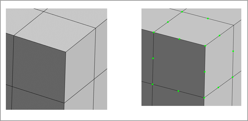
🔍 Tip: To visually inspect nodes in ANSYS Mechanical, activate the “Node” selection filter, then drag a selection box around your element. Nodes will appear highlighted, often in green.
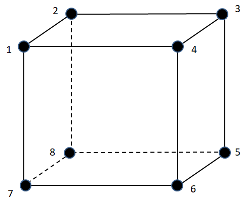
The figure below shows a depiction of 20 node element.
Why Do Mesh Nodes Matter?
- Accuracy: The number and placement of nodes affect the fidelity of your results. More nodes → better resolution, but higher computational cost.
- Boundary conditions: Loads, constraints, and contacts are applied at nodes. The density and location of nodes influence how realistically these conditions are simulated.
- Post-processing: Most results (stress, strain, temperature) are stored at nodes or extrapolated to them for visualization.