An FE solver computes displacement and force results at the element nodes . The shape function is used to interpolate the nodal results onto the interior of the element.
Unlike displacements and forces, strains and stresses are not computed at the nodes. They are computed at specific locations called “integration points” within the element. Integration points are also called Gauss Points. The calculated stresses and strains are extrapolated out to the nodes.
The number and location of integration points depend on the element type and the chosen integration scheme.
Reduced vs. Full Integration:
- Full integration uses the standard number of Gauss points required for exact integration.
- Reduced integration uses fewer points, which can speed up computations but may introduce numerical instabilities like hour glassing in under-integrated elements.
Location & Number of Integration Points
- 1D Elements (Beams, Bars): Typically 2 or more Gauss points.
- 2D Elements (Shells, Plane Stress, Plane Strain, Axisymmetric): Typically 2×2 or higher quadrature.
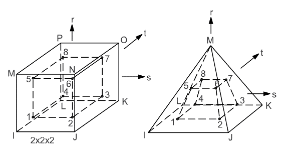
- 3D Elements (Solids): Hexahedral elements often use 2×2×2 (8 points) or higher.
- Tetrahedral Elements: Typically use a different integration scheme, such as 1-point integration.
ANSYS Commands Related to Integration Points
PRNSOL, S, ALL→ Prints stress values at nodes (extrapolated from integration points).PLESOL, S, ALL→ Plots stress at integration points.ETCONTROL→ Allows control over element integration settings.
See examples of elements showing nodes (i,j,k..) and integration points (1,2,3..) below:
To learn more about how integration points fit into the overall picture, you can take a look at this article summarizing basis structural FEA theory.