“There is too much penetration 594 contact points of the 3D contact elements“.
Messages regarding contact penetration such as the one shown above are often seen during ANSYS structural simulations. Some people get confused as to reason and purpose of this message. In this post we will discuss some aspects regarding contact penetration.
1. This message is informational but is neither an error message nor a warning message.
ANSYS solver displays a variety of messages during the solution process. Some of these are labelled as warning messages (such as contact status abruptly changing), while others are labelled as error messages (solution failed to converge).
As the labels suggest, an error message usually (but not always) is followed by the termination of the solution. A warning message is something which might be a red flag and is displayed to prompt the user to check certain aspects of the model for properness and accuracy.
In addition, sometimes the solver output displays messages which aren’t necessarily a cause for concern but could prove useful in multiple ways, especially when viewed in context. By context, we imply other messages that may have appeared, and the behavior of the solver – for example difficulty in converging to a solution indicated by load step bisections.
The penetration message is an informational message.
2. What is contact penetration?
Note: The content in this section is part of a separate article on contact formulations.
To answer this question we have to understand that there are two categories of contacts within ANSYS: 1) Normal Lagrange and 2) Penalty Based (Pure Penalty and Augmented Lagrange).
The two types of methods differ in how the contact interaction (between the contact and target surfaces) is treated mathematically.
With the Normal Lagrange method, the contact status is a step function. A contact point is either open (not in contact) or closed (in contact). This type of contact can sometimes result in a situation which is called “chattering” – A contact continues to cycle between open and closed states and the solver is unable to settle on a final contact state resulting from the applied loads and boundary conditions. In other words the model does not converge to a solution.
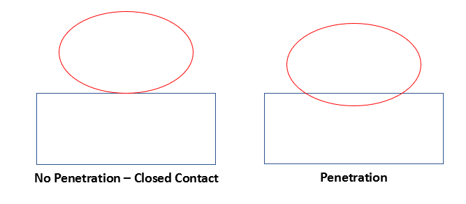
One way to address the issue of chattering is by introducing the concept of contact penetration. With this approach the nodes on the interfacing bodies are allowed to interpenetrate. This can be seen in the image below. The contact points on the red body are allowed to penetrate into the volume of the blue body.

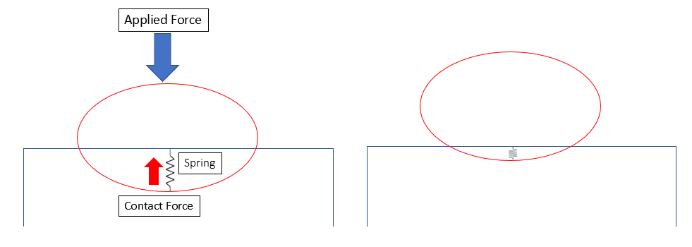
We know that in real life, physical bodies do not interpenetrate. This is why it is necessary to keep the penetration to a predefined minimum value. The way this is achieved is by introducing an artificial spring as shown in Fig 2. A stiffness value (Normal stiffness) is associated with the spring. This spring applies a force to essentially “pull” the red surface back and minimize the penetration. A “low enough” value of this penetration is required to achieve a converged solution. This value depends on various factor including the mesh size, and is governed by the contact’s “Penetration Tolerance” (TOLN) property. The default value for the penetration tolerance is 0.10 or 10% of the underlying element size.

3. What does this message mean?
If the amount of penetration at a contact pair is more than a predefined value ANSYS will report this to the user. This just means that the solver is in the process of achieving the desirable level of penetration. In some cases this message will disappear after a few iterations. In other cases, this may be indicative of another issue within the model.
If this message continues to appear along with difficulty in converging to a solution, one may take steps to identify and mitigate the source of instability within the model.
4. Using this message to debug an unstable model
Figure 3 shows a scenario where the model is facing difficulty converging to a solution. We also note that there is a warning message preceding the penetration message.

The warning message informs us of an “abrupt” contact status change. It also specified the real ID of the contact (593). This is a valuable clue. We can deduce that the contact with the real ID 593 is undergoing rapid status changes and is also seeing too much penetration.
The next step would be to determine which contact in the model is associated with this real ID. One way to do this in workbench is by inserting a contact tool and identifying the contact with real ID 593.
Figure 4 shows the initial contact information as processed by the contact tool. We can right click on the contact definition with “Real Constant” 593.

Now that the contact has been identified we can consider the following aspects:
- Is the geometry modelled correctly?
- Are the loads and boundary conditions correctly defined?
- Is the mesh sufficiently fine and of sufficient quality?
- Are the contact surfaces correctly defined?
- Do we need to apply the load more slowly (add more sub-steps)?
- Do we need to consider the effects of material non-linearities and element distortion?
- Do we need to consider changing the contact settings (contact type, interface treatment, contact stiffness, damping force etc.)
Paying attention to the above points (not necessarily in the exact order) can greatly help in determining the source of the instability, and in making the changes required in order to achieve a model that exhibits stable behavior.
In my experience, the two most important factors to consider when debugging too much penetration are the mesh quality and the normal stiffness factor. The default normal stiffness factor is 10.0 for bonded contacts and 1.00 for non-bonded contacts. Reducing the 1.00 to something like 0.20 often greatly helps with the excessive penetrations and non-convergence issues.
5. What about changing the penetration tolerance?
It is possible to adjust the penetration tolerance to make it more “forgiving”. The default of 0.10 may be increased to say 0.15 (15% of underlying element size) which could certainly aid in convergence. However, as we have already stated, contact penetration is a numerical feature and has no physical meaning. If we loosen the contact penetration to allow more penetration, then we must also ensure that the accuracy of the results is not compromised to an unacceptable degree.
One way to do this is to ensure that the contact penetration is “small” relative to the local displacements. A good check is to add the contact result Penetration to the local displacement and compute a back-of-the-envelope strain calculation. This helps determine if the penetration is significantly affecting the stress calculations. An example is shown below [1].

