The objective of this article is to discuss some aspects of applying bolt pretension in ANSYS workbench. It is not uncommon for ANSYS users to experience modelling difficulties when applying bolt preload such as the model not running, the solution not converging, or obtaining results which seem unrealistic. This article can be seen as a guide in order to accurately and efficiently simulate bolted connections.
We will discuss this subject in several points:
1. Solid Body vs Line Body
The bolt may be represented by a 3-D solid body a 1-D line body. Both methods have their pros and cons. We will not go into the details of each method since that is a detailed topic in itself and there is plenty of high quality work that is available on this subject. Here is a link to a well written paper that goes into various details regarding bolt modelling methods:
The work documented in this paper was done in ANSYS APDL (classic) but the content is also relevant to ANSYS Workbench.
2. Optimize the Contact Definitions
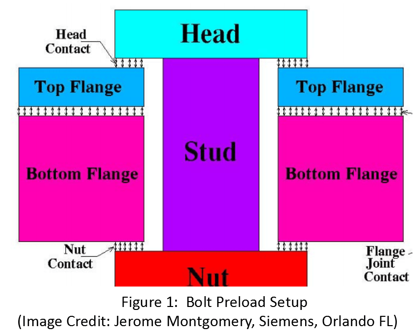
Figure 1 shows the cross section of a bolted flange assembly. This image was taken from the paper referenced under point 1 and we shall refer to it during our discussion.
- Bonded vs Frictional
In real life, the head contact and nut contact are frictional. Theoretically, the head and the nut can slide on the flange surfaces. However, in most applications, this sliding is very small and one may consider defining bonded contacts at these locations. Depending on the objective of the analysis the inaccuracy associated with this simplification may be negligible. It is important to realize that this is not universally true and it must be viewed in relation to the objective of the analysis.
- Adjust to Touch vs Add Offset
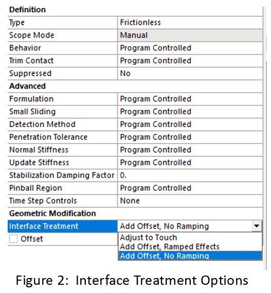
The contact between the top and bottom flange should be defined as frictional. Under “interface treatment” we can select Adjust to touch or Add Offset (as shown in Figure 2).
Selecting Add Offset can sometimes cause convergence difficulties.
With Add Offset (zero offset) the geometrical gap between the two flanges will be treated as a gap. The two flange faces actually making contact will depend on a number of factors including the gap size, the mesh quality, and the applied load.
In most cases, we may not care about this gap at all and we may intend for the two flanges to be effectively face to face even before the preload is applied. In order to simulate a “closed” or “touching” contact, the interface treatment should be set at adjust to touch. Any gap between the two flanges will be “filled” by ANSYS (without modifying the physical geometry) and the two flanges will be modelled as touching. This will result in a more robust and realistic model.
3. Apply Pretension to Bolt Body OR Bolt Face
If a solid body is used, the bolt preload can be applied to the bolt body or to a face.
If it is applied to the bolt body, then a coordinate system for preload application must be specified. The pretension direction will correspond to the Z-axis direction of this coordinate system, which must be parallel to the shaft of the bolt. Additionally, the X-Y plane of this coordinate system must pass through the body of the bolt. The coordinate system does not need to be centered at the bolt shaft.
For application to a face, the free length of the shaft should be selected. In this case, ANSYS automatically defines an appropriate internal coordinate system and the user does not need to manually specify a coordinate system.
4. Define Pretension by Load OR Adjustment
The pretension can be defined by Load or adjustment (as shown in Figure 3 below).

As the name suggests, load will apply the tensile load to the bolt. This is the load due to the installation torque (a quick and simplified calculation relating torque, preload force and bolt diameter : T = 0.2FD).
Adjustment refers to how much the bolt will stretch due to the applied tension.
If you think of the bolt as a spring and apply Hooke’s law to it, F=KX then X represents the adjustment (F is the applied load and K = AE/L is the bolt stiffness).
In general, applying a displacement is a more robust way of applying an input load to an FE model as opposed to the force which would result in that displacement. This is why sometimes defining preload by load can result in convergence difficulties. In such scenarios applying the load via adjustment (i.e. the corresponding X value) can be beneficial.
5. Make Sure There are No Duplicate Preload Applications
If there are multiple preload applications to a single body or face, the solver will not start and ANSYS will return an error message. There can only be one preload definition per body or face.
6. Do Not Apply Other Loads in the Pretension Application Time Step
This is a very important but often over looked point. The preload should be applied in a time step dedicated to the pretension.
There should be no other loads applied in the preload time step (usually the first time step in the analysis). If other loads need to be applied, they should be applied in subsequent steps. Not adhering to this may result in convergence difficulties and / or erroneous results.
7. Lock the Pretension in Subsequent Time Steps
If there are multiple time steps in the analysis, the pretension should be locked in the subsequent steps (unless there are specific reasons not to).

If the pretension is explicitly defined in the subsequent time steps ANSYS would consider it as a reapplication of the pretension. It will return a warning message which may be followed by the model terminating. As the name suggests, “Lock” preserves the pretension setting from the first step and is representative of real-world behavior.
8. Consider Applying Temporary Constraints
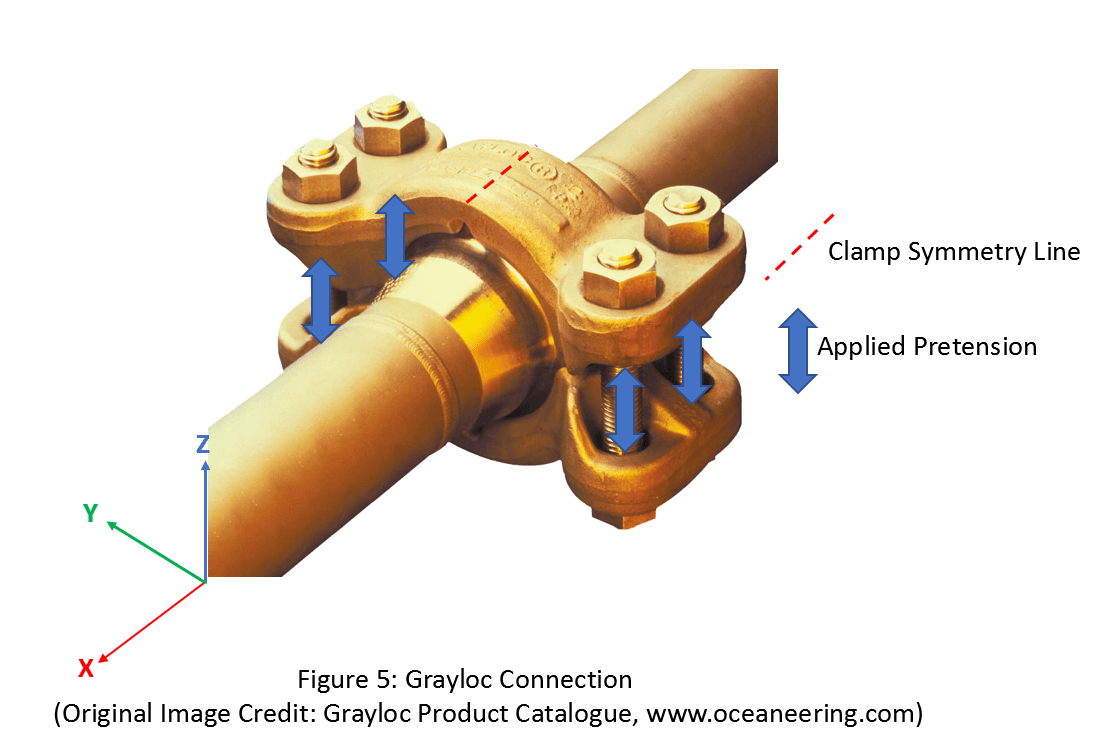
Sometimes it is advantageous or even necessary to apply what I call “temporary” constraints during the pretension application step. These constraints may help build a more accurate and stable model. Consider the Grayloc connection shown in Figure 5.

If the pretension is applied as shown without any other degree of freedom constraints on the clamp, the clamp will be free in all direction. As the pretension is applied, depending on how the contacts are defined, the clamp segments may have a tendency to spin (Moment in the X direction) or translate (displacement in the X direction). Convergence may be very difficult to achieve. One of the ways this issue can be resolved is by applying a temporary constraint.
We can fix the nodes on the line of symmetry on the top and bottom surfaces of the clamp (shown in dotted line) in the X and Y directions. This will prevent the undesirable rotation and translation, while allowing the Z direction translation necessary for the clamping process. However, this constraint should be deactivated in the subsequent time steps. If it is not deactivated, then the clamp will be over constrained and the simulation may return inaccurate results.
I hope this article was useful. If you have any questions or comments feel free to post a comment or reach out to me directly, and I will do my best to be of help.


