When it comes to numerical simulations, the results are as good as the mesh – By this, we mean that a “poor” mesh will give a “poor” or inaccurate results. This is why ensuring that the mesh is “good enough” is essential to producing reliable results.
There are multiple ways of verifying that a model mesh is acceptable. One of these is conducting a mesh independence study. You can view this article on mesh independence study for more information.
While mesh independence study is great, it does require a significant amount of time – you need to have multiple models with different meshes and results. Additionally, the study is usually best performed for isolated regions of the model as opposed to taking a global view.
Fortunately, there are several tools within ANSYS which let us quantify the overall mesh quality during (and after) the mesh generation phase.
If you look under Mesh –> Statistics –> Mesh Metric you will find a drop down menu as shown in the image below.

You can pick from a number of different mesh metrics and ANSYS will provide the mesh statistics for the selected metric. If you need more information on these you can read this article on mesh metrics.
I will only mention two of the most commonly used metrics – Skewness and Orthogonal Quality. There is literature from ANSYS which provides useful guidelines and recommendations for all mesh metrics including skewness and orthogonal quality.
Check out FEA Tips eBook – All Models are Wrong
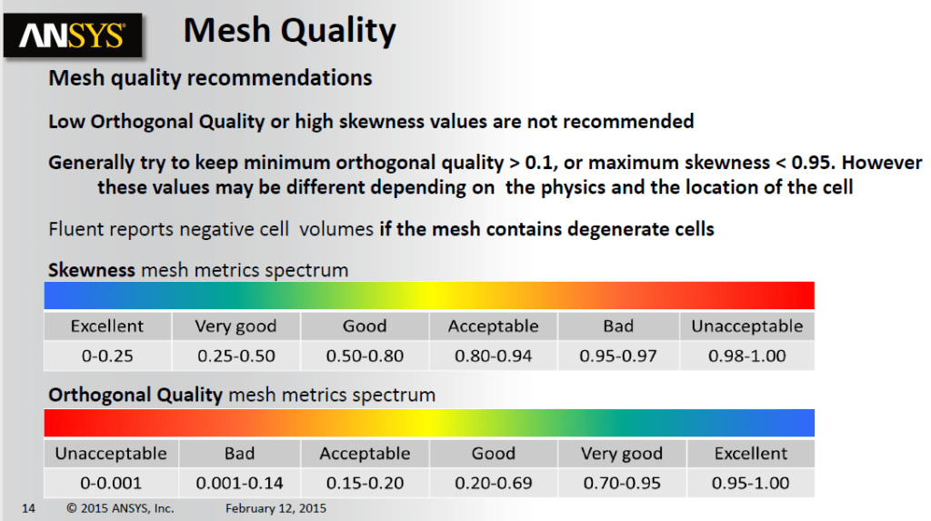
Here is an excerpt from some ANSYS training material. It can be seen that low orthogonal quality and high skewness values are generally not recommended. Both metrics vary from 0 to 1.

These recommendations are mainly for meshes for CFD applications, and in general meshes for structural models are more forgiving. Nonetheless, these guidelines may also be used for structural models to achieve a high quality mesh.
Below is a link for ANSYS training material which goes into more details on the topic of meshing.
Using Shape Checking
In ANSYS workbench, you can activate automatic shape checking. This can be done by going to Mesh, Quality, Check Mesh Quality and picking an option from the drop down menu. The options are:
- No
- Yes, Errors and Warnings
- Yes, Errors
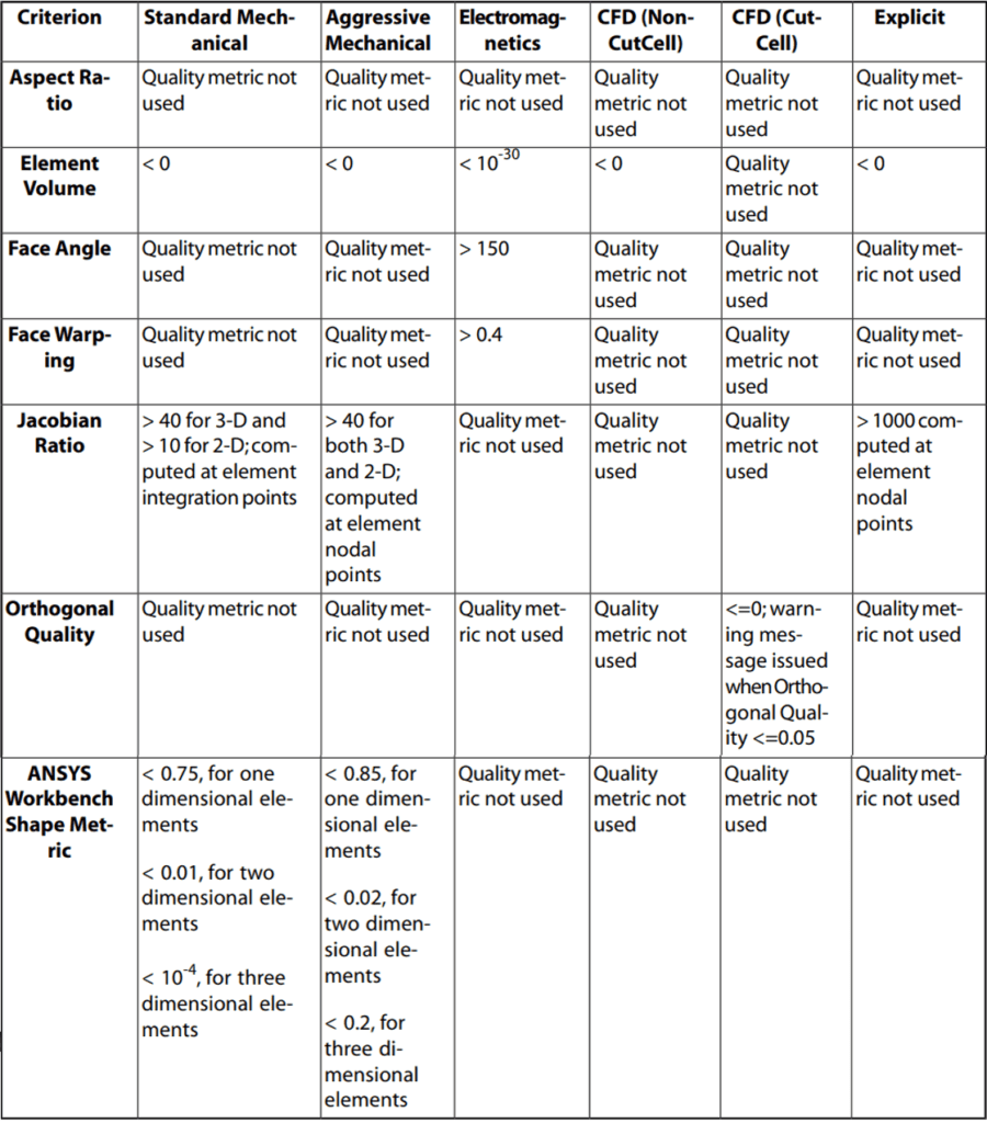
If this is set to yes, then the meshing algorithm will ensure that the mesh generated meets the specific requirements for the Physics that is being modeled. The following is an excerpt from ANSYS Meshing User’s Guide:
For automatic meshing, shape checking ensures a quality mesh based on specific error limits. The following table presents the shape checking limit criterion for each option. If the results of any test are outside of the limits shown, the mesh will fail. For example, a Jacobian ratio greater than 40 computed at element nodal points will cause a mesh failure when using the Aggressive Mechanical option.

From the table above, you can notice the differences between Standard Mechanical Shape Checking and Aggressive Mechanical Shape Checking. The aggressive option is more stringent and ensure a higher quality mesh that standard mechanical shape checking. Aggressive Mechanical Shape Checking is especially recommended for models with non-linear materials and plasticity modeling.
