One of the useful features in ANSYS workbench is the ability to export a result to a text file. The text file will include the node numbers, nodal coordinates and the nodal results. The export option can be accessed by right clicking on a result as shown in the image below.

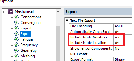
If the exported file does not include the nodal coordinates, then you would want to check the export options to make sure that “include node location” option is activated. The export option can be accessed via the Mechanical menu as shown below.

This method exports the nodal coordinates in the global coordinate system. As an example, the figure below shows the X direction deformations for nodes in a local coordinate system labelled Joint_3_LCS. Columns B,C and D report the nodal coordinates in the global CS.

It is possible to report the nodal coordinates in a local coordinate systems as well but it is a multi step process.
Check out FEA Tips eBook – All Models are Wrong
There is an APDL command LOC_DEF() which exports the nodal locations at a time step. This command can be inserted in workbench through a user defined result. The locations will be reported at the time step, and in the coordinate system selected. See the image below for reference.

The figure below shows how the exported file would look like. Note that columns B, C and D still show what is essentially the nodal coordinates in the global coordinate system.

You can use this command at a time step with zero displacements. At zero displacements the nodal locations (LOC_DEF) are equal to the X coordinate of the nodes in the local CS.
If a time step with zero displacements is not available, then you can export both the nodal locations and deformations (separately). Now you can subtract the nodal deformations from the nodal locations in the local CS to get the nodal coordinates. As an example, the X location for node number 465720 in the coordinate system named Joint_3_LCS is (687.61 + 0.95766 = 688.567).
If you found this article useful, you may be interested in our eBook on FEA.
