Introduction
In this article, we will discuss some aspects of ANSYS contact theory and relate those to the contact formulation options.
ANSYS offers five different contact formulations. If you go to the details of a contact definition and under Advanced, click on Formulation, you will see the following drop down menu:

We will expand on Augmented Lagrange, Pure Penalty and Normal Lagrange – MPC and Beam are relevant for bonded and No Separation contact. You can read about MPC contacts here.
Penalty vs Lagrange Methods
There are two basic methods of contact formulation in ANSYS: Penalty based and Lagrange Based.
The two types of methods differ in how the contact interaction (between the contact and target surfaces) is treated mathematically.
With the Normal Lagrange method, the contact status is a step function. This type of contact can sometimes result in a situation which is called “chattering” – A contact continues to cycle between open and closed states and the solver is unable to settle on a final contact state resulting from the applied loads and boundary conditions. In other words the model does not converge to a solution.
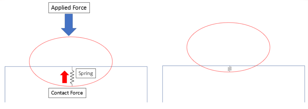
One way to address the issue of chattering is by introducing the concept of contact penetration. With this approach the nodes on the interfacing bodies are allowed to interpenetrate. This can be seen in the image below. The contact points on the red body are allowed to penetrate into the volume of the blue body.

We know that in real life, physical bodies do not interpenetrate. This is why it is necessary to keep the penetration to a predefined minimum value. The way this is achieved is by introducing an artificial spring as shown in the Figure below.

This spring applies a force to essentially “pull” the red surface back and minimize the penetration. A “low enough” value of this penetration is required to achieve a converged solution. This value depends on various factor including the mesh size, and several contact settings.
It is best to view the differences between the two methods in a tabular form:

The Lagrange method is more accurate since it better represents real life – i.e. no interpenetration. However, this comes at a computational cost in the form of higher run times.
What is the Augmented Lagrange Method?
The main reason to choose the Lagrange Method is its accuracy and the main reason to choose the Penalty method is its low computational cost. But what if we find an optimum formulation which is essentially the best of both worlds? Something that provides both acceptable accuracy and run time. This is where the Augmented Lagrange Method comes in. This is also the default contact formulation in ANSYS.
Check out FEA Tips eBook – All Models are Wrong
The Augmented Lagrange Method allows minimal penetration but is able to achieve robustness and low run times. The table below shows a comparison of the three contact methods.

The last column in the table above shows the symbols for the various parameters which the algorithm uses to determine the contact status.
FTOLN is based on the thickness of the contact element. A value of 0.10 indicates 10% of the element thickness.
FKN ranges from 0.01 – 10

Using the Stiffness and Tolerance Factors to aid in convergence
If you get a warning message related to too much penetration you have several options:
- Use the Normal Lagrange method – This will take penetration (and contact stiffness) out of the equation (no pun intended!)
- Reduce the normal stiffness factor
- For bending dominated problems, use 0.01
- For bulk deformation problems, use 1.00
- Reduce the Penetration tolerance factor to 0.01
Further Readings
ANSYS Contact Technology Guide is an essential read. You can search the pdf for relevant topics and get quick and reliable information.
ANSYS APDL Element Reference may be used to study the contact capabilities of various elements.
Here is a guide on best practices for contact modeling.
