It is often useful to be able to calculate the force and moment reactions along a cross section in ANSYS workbench. While this is doable, a specific set of steps must be followed to accomplish it. In this article we will list these steps.
Problem Statement
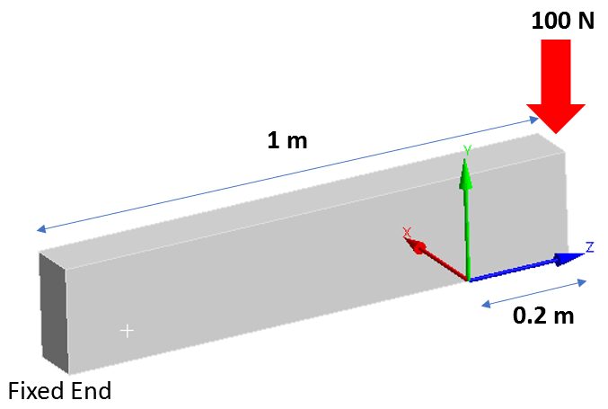
Consider a 1m long cantilevered beam with a rectangular cross section, as shown below. A 100 N force is applied to the free end. We want to confirm that the a bending moment of 20 Nm is reported by ANSYS when measured at a cross section 0.2 m from the free end.
Post Processing Steps
The first step is to run the model and get a solution. The post-processing steps are:
- Create a coordinate system at the required cross section (in this case at 0.20 m from the free end).
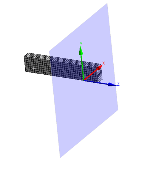
- Create a plane centered at this coordinate system as shown below
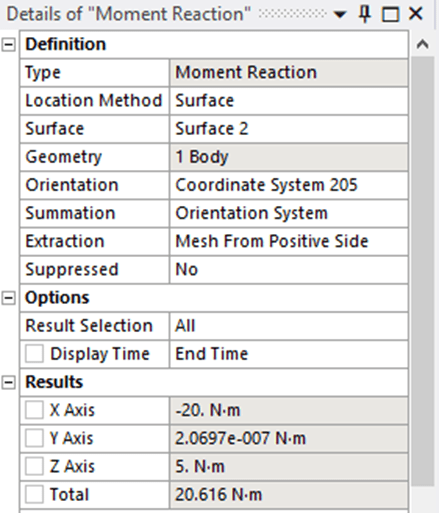
3. Insert a moment probe with the following settings:
- Location Method: Surface
- Surface: The surface that you created in Step 2
- Orientation: The coordinate system that you created in Step 1
- Summation: Orientation System
The results can be see in the image below. As you can see, the Mx is reported correctly as -20 Nm. You can change the setting under “Extraction” to obtain the + or – sign with the moment reaction.