This article is a supplement to our Bolt Stress Calculator.
Bolt stress calculation is one of the most common types of design calculations performed. In this article we will consider a simple case of a preloaded bolt subjected to a tensile force and a bending moment. We will calculate the closed form solution (hand calculation) for the maximum von-Mises stress at any point in the bolt and will compare it to a simple simulation in ANSYS.
The following excerpt from mechanicalc summarizes bolt stress calculation.
“The stresses in the bolt are calculated per the equations shown in the table below:

where At is the tensile stress area and As is the shear area (either the nominal area if the shear plane is in the shank or the minor area if the shear plane is in the threads).
We see that the bending stress is dependent on diameter, d, which is the either the nominal diameter if the maximum moment is in the shank or the minor diameter if the maximum moment is in the threads.
The von Mises stress is calculated by:

In the equation above, n is a load factor which is applied to the tensile, bending and shear stress but is not applied to the preload stress. The load factor is related to the factor of safety, with the difference being that it is a factor that is applied to the loads or stresses to ensure that the bolt stress remains below the allowable stress.”
For our simple example, we will only consider the preload, tensile force and a bending moment. We will consider n to be 1.
An important thing to note is that the calculation above calculates the maximum stress at any point in the bolt. For a uniform cross section the preload and tension will produce a uniform stress field through the cross section and along the shaft (i.e. everywhere) but this is not true for bending. Bending of a shaft has the tendency to produce maximum tensile stress on the “outermost” fibers (since they elongate) and maximum compressive stress on the “innermost” fibers (since they shrink). The “middle fibers” stay at a state of zero stress (due to bending) since the effect of tension and compression is neutralized there (hence the term neutral axis).
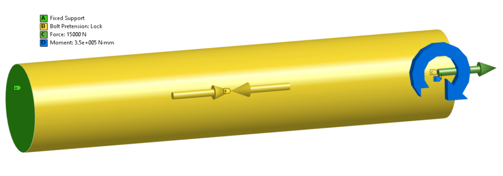
Let us look at a simulation of bolt stress in ANSYS Mechanical. The bolt is modeled as a cylinder with one end fixed. The other end is fixed during the preload application, and free in the subsequent load step (when the force and moment are applied). Default ANSYS material properties for structural steel were used (This article discusses bolt modeling in ANSYS in detail).

The table below lists the relevant parameters for two test cases:

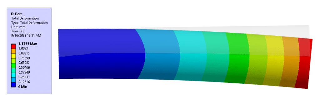
The image below shows the total deformation for Case 1, at true scale. The undeformed bolt geometry is also shown.

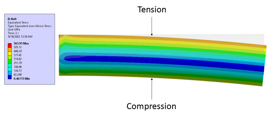
Below is an image showing the von-Mises stress distribution through the shaft. Note the bands of constant stress indicating regions of tension and compression.

This next image shows the location of the maximum stress on the bolt shaft. There are a couple things of note here:
- The maximum stress reported (565.95 MPa) is localized on the edge where the fixed boundary condition is applied. This is a numerical artifact and is not “real”.
- The maximum stress on the shaft occurs where the maximum tensile stress due to the bending moment enhances the tensile stress due to preload and tensile force. This happens on the outer fibers of the cylinder.
- The length of the bolt has no impact on this calculation.

Finally, we can perform a comparison between the hand calculation and the FEA results. The hand calculation matches very closely with the FEA results.

