Background on numerical analysis
In this article we will describe what is meant by Implicit and Explicit in the context of numerical analyses. There are several concepts to consider and it is best that we present them under different topics and build on our understanding of each concept. What follows is some background on numerical analysis. This background can help enhance your understanding of explicit and implicit techniques. But if you wish, you may skip this section and go straight to the Implicit vs Explicit time integration section further below.
Reality is spatial and sequential
We live in a world whose material building blocks are space and sequence – All physical events are bound by space and occur in a sequence.
We define coordinate systems and time
We represent space via a 3-Dimensional coordinate system and sequence by time. 3-D works for us because every point in space can be defined by a linear combination of 3 independent vectors. Time represents the sequence of events and is the fourth dimension. Therefore, all physical events are bound by four dimensions.
Space and time are continuous
By continuous we mean that if you consider two points in space or time, then there are infinite points between them. You can keep dividing a line into small segments but you will never reach a division whose length is zero. Similarly there are infinite divisions of a unit of time.
All physical events are continuous
Without exception, all physical events are bound by space and time. Since space and time are continuous it implies that all events are also continuous.
The effects of any of the four dimensions are often neglected in engineering problems
It is common to model an object as existing in 2D space. Similarly, time is often not considered for engineering problems. This does not mean that the ignored dimensions have no effect on the solutions. It just means that we are ignoring the effect of those dimensions. Fortunately, in many cases the accuracy of a solution is acceptable even if several dimensions are ignored.
Analytical solutions of physical problems respect continuity
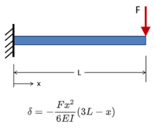
Consider a cantilever beam with a point load F acting at the free end as shown. The formula gives the exact deformation of the beam along any point on the beam. There are infinite points on this beam along the length (continuity). You can pick any point and the equation will give you the exact solution. This is an analytical solution.

Numerical solutions of engineering problems do not respect continuity
Numerical solutions are approximations of analytical solutions. They are essentially independent of analytical solutions. This makes them very useful because the behaviors of majority of the real world systems cannot be described analytically and we resort to numerical techniques for answers.
Numerical solvers often discretize space and time
In order to calculate solutions to engineering problems, numerical solvers often discretize space and time. We know space discretization as what we call a finite element mesh. Generally, the finer the mesh the closer the results will be to reality and to the continuous analytical solution.
What about time discretization?
Time discretization refers to how a solver treats time. What segments to break up the time into and how to progress from the known solution at a given time step to calculate the unknown solution at the next time step. There are several methods for this and are referred to as time integration methods.
Implicit and Explicit Time Integration Techniques
Implicit and explicit refer to two approaches to time integration in numerical solutions of time-dependent (dynamic) problems. Let us now consider the basic math behind these two techniques:
consider a 1-D function F varying in t. The following is the basic thought process behind time integration:
Function at a given time step, F (tn) = known
Function at the next time step, F (tn+1) =?
Time step size, tn+1 – tn = Δt
Then,
F (tn+1) = F (tn) + F’ (tn) Δt
Where,
F’ (tn) = Δf / Δt
This seems reasonable. But it can be more complicated than it appears. The slope of a function may be rapidly changing. This means that F’ (tn) may be very different from F’ (tn+1). If this is the case then who gets to decide what slope to use for time integration? This is exactly where implicit and explicit methods come in!
Implicit time integration uses the slope at the unknown time step, F’ (tn+1) .
Note that this slope is unknown (yet the solver wants to use it to calculate another unknown). Numerical techniques such as the Newton-Raphson method may be employed to iterate to an acceptable value of the unknown slope (Read more about the Newton-Raphson method). The slope that is calculated numerically is not an explicit result. Rather, it is implicitly determined, hence the name Implicit technique.
Explicit time integration uses the slope at the known time step, F’ (tn)
The function F and hence F’ are known at tn. This means that F (tn+1) can be explicitly calculated. One can see that by definition an explicit analysis requires very short time increments, making explicit analyses suitable for ultra short time scale events – such as car crashes, blasts, ballistics, meteor impacts etc.
Static and Quasi-transient analyses are generally better suited for implicit integration schemes. By quasi-transient, we imply events that last more than two seconds – for example mechanisms and transient thermal analyses.
LS-DYNA and AUTODYN are two explicit solvers available in ANSYS.
Rigid body dynamics uses explicit time integration scheme. Transient structural analysis utilizes an implicit solver.
Static structural analysis does not involve real time but the time-steps (load steps) associated with non-linear analyses are solved via implicit time integration.
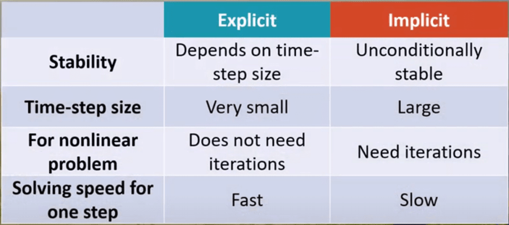
Here is a concise table taken from ANSYS rigid body dynamics video.

The table below expands on the comparison between explicit and Implicit Analysis.
| Entity | Implicit Time Integration | Explicit Time Integration |
| Function Slope Calculation | Implicitly by numerical methods. Calculated at future time step | Explicitly at the current time step |
| Suitable velocity / Strain to be modeled | Relatively much lower | Very high |
| Time increment | Relatively higher | Very low |
| Examples of ANSYS options | Static Structural, Transient Structural | LS-DYNA, AUTODYN, Explicit Dynamics, Rigid Dynamics |
| Examples of suitable problems | Static Structural, Transient thermal, Mechanisms | Car Crash, Shockwaves, Ballistics, Blasts |
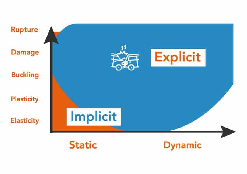
The plot below is a good graphic summarizing the suit abilities of explicit and implicit solvers:

[Image Credit: https://www.axirogroup.com/show-case/rops-simulation/]
We will discuss the differences between the various dynamic analyses options provided by ANSYS in another article.
Here is a great video from ANSYS explaining some of the concepts discussed in this article.
