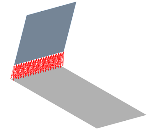
MPC contact is short for Multi Point constraint contact. It is one of the contact formulations available in ANSYS for bonded and No separation contact.
MPC contact is generally the best contact formulation choice for bonded and No separations contacts. The only time this might not be true is when MPC contact results in an over constraint (more on this later in this article).
The advantages of MPC contact
- MPC contact algorithm is not penalty based or Lagrange based (read more about Penalty and Lagrange based formulations).
- Contact stiffness is not required.
- MPC adds internal constraint equations to tie the displacements of the contacting surfaces.
- The individual DOF of the contact nodes are eliminated. Instead all the DOF are forced to have the same solution as that at a pilot node defined by the MPC equation.
- Due to the above MPC is an extremely efficient contact formulation.
- In the absence of material and geometric non-linearities MPC contact represent a true linear situation. Only one equilibrium iteration is required to solve the system of equations. This results in short run times compared to other contact formulations.
- For large displacement models the MPC equations will update at each equilibrium iterations. This overcomes the limitation present with conventional constraint equations.
- Can be used for several scenarios where conventional algorithms would be difficult or impossible to employ.
- The following types of contacts are supported:
- Solid-Solid
- Shell-Shell
- Shell-Solid
- Beam-Shell
- Beam-Solid
- Unwanted gaps in CAD geometry can be accurately ignored without having to modify the geometry
Check out FEA Tips eBook – All Models are Wrong
The Limitations of MPC contact
- Over constraint can occur. A warning message such as the following may be seen:
One or more MPC contact regions or remote boundary conditions may have conflicts with other applied boundary conditions or other contact or symmetry regions. This may reduce solution accuracy.
This message means that a degree of freedom is subjected to multiple constraints. In some situations, the solver attempts to automatically remove some of the constraints. In other cases it may fail to run. From a practical stand-point, over constraint can occur when:
– A displacement or temperature boundary condition is applied to the MPC contact surface nodes
– When multiple constraint equations are defined for the same surfaces
– When rigid bodies and joints are connected via MPC contact - MPC contact does not support connecting Rigid-Flexible bodies if the Rigid body is modeled via a primitive segment (circle, cylinder, cone or sphere)
- There are several other specific cases where MPC contacts may not work or are not ideal. The details of this can be read under ANSYS Help section 10.6
