Introduction
Generating a finite element (FE) mesh is as much an art as a science. The shape, order, and type of elements used can significantly impact the behavior of the model and the stresses and strains observed. ANSYS provides many ways to customize and optimize a mesh to one’s needs and likings. To this end, one of the customizations available is the Meshing Method. In this article we will look at the details of the various meshing methods available. But before that, we would like to discuss the various ways in which a FE mesh can be categorized.
Mesh Categorizations
A finite element mesh can be categorized by:
- Number of dimensions
This refers to a mesh being in one, two or three dimensional space. An ANSYS model can comprise of either 1D (Beam elements), 2D (Shell elements), 3D (Solid Elements) or a combination of the three types of meshes. Read more about Solid vs Shell elements. - Element Shape
The general mesh shape can be a triangular or quadrilateral. A 3D “triangular” element is referred to as a tetrahedron and a 3D “quadrilateral” element is called a Hexahedral element. - Element Order (linear vs Quadratic)
Element order refers to the number of nodes (what is a mesh node?) comprising the element, and is one of the properties that determines the displacement response of an element. Read more about linear vs quadratic elements. - Mesh Structure
A mesh can be structured or unstructured. As the names suggest a structured, mesh is “orderly” whereas an unstructured mesh is not orderly. The locations of the nodes of a structured mesh are well defined, predictable and from a programming point of view, are implicitly connected. This allows for efficient programming by way of storage of data and results in efficiencies in run time and use of system resources. The opposite is true for unstructured meshes. Below is an image comparing the two types of meshes:
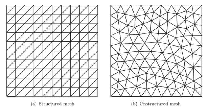
There are several advantages and disadvantaged of structured and unstructured meshes as summarized in the table below. In general, structured meshes are memory efficient and are associated with faster run times. The main advantage of unstructured meshes is that they can be generated on complex geometries which is often not an option with structured meshes. We can summarize this information as follows :

5. Mesh Quality
The “quality” of a mesh is determined by various mathematical parameters and lies on a spectrum. Read more on mesh quality metrics. Sometimes low quality mesh elements are referred to as degenerate (as opposed to non-degenerate).
To be more precise, a degenerated mesh element is an element whose characteristic face shape is quadrilateral, but it is modeled with at least one triangular face. Such elements are often generated to model transition regions between fine and coarse meshes, or to model irregular and warped surfaces.
6. Meshing method
Meshing method is the algorithm used by the software to generate the mesh. We will now discuss this topic in detail.
Meshing Methods in ANSYS
If you look under the “Method” dropdown under mesh definition you will get the following:
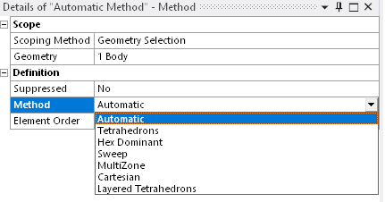
Let us discuss each one of these options individually. The majority of the information below has been derived from ANSYS help (setting the method control for solid bodies).
Automatic
By default, the application uses the Automatic Method control, which attempts to sweep (more on this later) a mesh for solid (3D) models and quadrilateral element generation for surface (2D) body models. If solid bodies can’t be swept, the Patch Conforming Tetrahedron method (more on this later) is used.
Tetrahedrons Method
This method attempts to created a fully tetrahedral mesh. Below is a four-node tetrahedral element:

You have the choice to pick from two meshing algorithms:
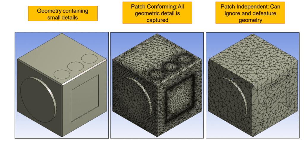
- Patch Conforming Method
This is a bottom-up approach – The meshing process starts from edges, faces and then moves into the volume. All faces and their boundaries are respected (conformed to) and meshed. This generates a high quality, clean mesh. - Patch Independent Method
This is a top-down approach – The volume mesh is generated first and is projected on to the faces and edges. Geometrical features such as faces, edges and vertices are not necessarily conformed to. This method is more suitable for poor quality (dirty CAD) geometry.
Hex Dominant Method
This method attempts to create a mesh dominated by hexahedral elements.

This option is typically recommended for bodies which cannot be swept. A hex mesh is generally preferred to a tetrahedral mesh. At this point, it is relevant to compare and contract Hexahedral and Tetrahedral meshes. The image below is a good reference:

Sweep Method
A sweep mesh generates a mesh on one surface (source face) of a body and literally “sweeps” along the length of the body up to another surface (target face). The mesh pattern is identical along the length of the body.
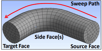
The user can control the number of mesh divisions along the sweep path.
A swept mesh requires that the body is “sweepable” – The source and target meshes must be topologically identical. Hex / wedge elements may be created with the sweep mesh. As one can see, for clean geometries the sweep mesh has potential of creating highly efficient meshes.
You can read more about the sweep method here : Understanding the Sweep Mesh Method in Ansys.
MultiZone Method
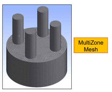
The MultiZone mesh method provides automatic decomposition of geometry into mapped (sweepable) regions and free regions. When the MultiZone mesh method is selected, all regions are meshed with a pure hexahedral mesh if possible. To handle cases in which a pure hex mesh will not be possible, you can adjust your settings so that a swept mesh will be generated in structured regions and a free mesh will be generated in unstructured regions [4].
The MultiZone method can be useful when working with geometries whose cross sections are’nt identical along the length but regions of swept meshed are desired.
Cartesian Method
The Cartesian method creates unstructured hexa mesh of mostly uniform size, aligned to the specified coordinate system, and fits it to the geometry. The element size should be smaller than the thickness of the model to prevent the mesher from defeaturing (not capturing) that portion of the model. Alternatively, the defeaturing could be helpful to eliminate “dirty” geometry smaller than the element size.
This method is useful when the geometry features align well with a coordinate system and a regular mesh is desired. Models for explicit dynamics, organic models (models without many feature edges), process industry and electronic components are good examples that could benefit from this mesh method. This method is also recommended for simulating the printing process in Additive Manufacturing [4].
Layered Tetrahedron Method
The Layered Tetrahedrons mesh method creates unstructured tetrahedral mesh in layers based on a specified layer height and fits it to the geometry.
This method can be used for simulating the printing process in Additive Manufacturing as the build parts must conform to a mesh with fixed step sizes in the global Z direction [4].
Layered tetrahedral meshing was first introduced for additive manufacturing simulation in 2019 by ANSYS®. Its
aim is to simplify the representation of the small detailed geometry of AM parts without increasing the level of
complexity of the model. The tetrahedral shape of the elements allows the meshing algorithm to achieve a better fitting mesh with only small element distortions. Despite the higher number of elements in the simulation model using this meshing method, accurate results can be achieved in less time than with Cartesian meshes [3].
Particle Method
Particle Method is available only when the Physics Preference is set to Explicit in the Mesh Details view and for bodies with Reference Frame set to Particle. Particle Method generates cloud of particles of specified diameter within the body.
Note:
- Particle Method does not support multi body parts.
- Particle Method supports only solid bodies.
- Solid bodies must have water-tight facets to be meshed with Particle Method [4].
Feature Updates
Ansys routinely updates its software to include new features and quality of life improvements. Links to articles documenting such updates will be listed here:
Ansys 2024 is enhanced with features related to:
- Automatic (PrimeMesh)
- Tetrahedrons Mesh Method – Patch Conforming Algorithm
- MultiZone Method
References
[1] Assessment of spurious mixing in adaptive mesh simulations of the two-dimensional lock-exchange
[2] Introduction to ANSYS Meshing, Module 01
[3] A Comparison of Layered Tetrahedral and Cartesian meshing in Additive Manufacturing Simulation
[4] ANSYS Help
