We recently posted an article discussing various ANSYS contact settings. One of the settings section was left out for a dedicated article which is the subject of this article. We are talking about Geometric Modification. This option appears below the “Advanced” option of the contact settings tree.
The available options vary based on the contact type. If the contact and target surfaces (Contact vs Target explained) are faces (as opposed to edges), you get the option to modify the geometries.

The content below has been derived from ANSYS help documentation.
Contact / Target Geometry Correction
There are three options available for contact geometry correction: None, Smoothing, Bolt thread. For the target geometry correction, only smoothing is available (Contact vs Target explained).
Smoothing
This feature enables you to improve the accuracy of circular edges (2D) and spherical or revolute surfaces (3D) by evaluating the contact detection based on the exact geometry instead of the mesh. This feature enables curved geometries to be analyzed more effectively using meshes with dropped midside nodes (linear elements). Linear elements (What are linear elements?) are not able to capture (follow the contours of) curved edges accurately.
Note:
- The Behavior properties Symmetric and Auto-Asymmetric are not supported.
- To avoid having the application incorrectly modify the geometry of a contact surface that has drastically deformed, do not use the Smoothing feature during an analysis that has specified Large Deflection (Non-Linear Geometry).
With smoothing selected you get a contact orientation option as shown below:

- Program Controlled: This option is only valid when the contact scoping is on a sphere or a single, simple cylinder. The option becomes invalid when the specified scoping:
– Includes more than one face.
– Is on a single cylinder face, but the cylinder includes more than two edges.
– Is on a single cylinder face with two edges, but the CAD package does not identify it as a cylinder.
If the Program Controlled option is not valid, you can use the Revolute Axis option to manually identify the cylinder. - Sphere Center Point (3D) or Circle Center Point (2D): When one of these properties is selected, the Center Point property also displays. The Center Point property provides a drop-down list of available coordinate systems, Global as well as user-defined. As needed, create a local coordinate system at the center of your sphere.
- Revolute Axis: You use this option for 3D revolute surfaces, such as a cone or a cylinder. The definition of the revolute surface is computed using an internal axis definition. When Revolute Axis is selected, the Starting Point and Ending Point Properties are displayed. These properties define the coordinate systems that are used to define the axis around which the contact smoothing is oriented.
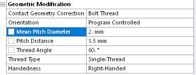
Bolt Thread
This geometry correction option enables you to model bolt threads. For a 2D axisymmetric model, only edge-to-edge scoping is supported. For a 3D model, only face-to-face scoping is supported.

Tip: When you specify the Bolt Thread option, it is strongly recommended that you have a refined mesh.
In order to use the Bolt Thread option, note the following.
- For 3D models, when the Orientation property is set to Program Controlled, the edges specified for the Contact and Target properties of the selected cylinders must be circular edges.
- The Contact Geometry Correction property is available for all contact Type settings except for Bonded
- The Behavior properties Symmetric and Auto-Asymmetric are not supported.
- It is recommended that you do not set the Detection Method to either Nodal-Normal To Target or On Gauss Point.
- The diameter of the solid model (bolt and nut bodies) should be based on the major diameter (d).
Interface Treatment
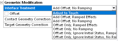
The interface treatment option becomes available (as shown below) if the contact type is set to Frictionless, Rough, or Frictional.


As the name suggests, interface treatment allows the user to specify the way in which the contact and target surface should interact with each other. These settings are especially useful (and sometimes necessary to be applied) when the geometric gap between the contact and target faces does not represent a real-life situation, yet you wish to model the contact behavior accurately. You can select the appropriate interface treatment and avoid the need to remodel the geometry. Other times, interference fit problems can also be modeled by using the right interface treatment settings.
The following options are available:
1- Adjust to Touch
2- Add Offset (Ramped / Not Ramped)
3- Offset Only (Ramped / Not Ramped)
4- Offset Only, Ignore Initial Status (Ramped / Not Ramped)
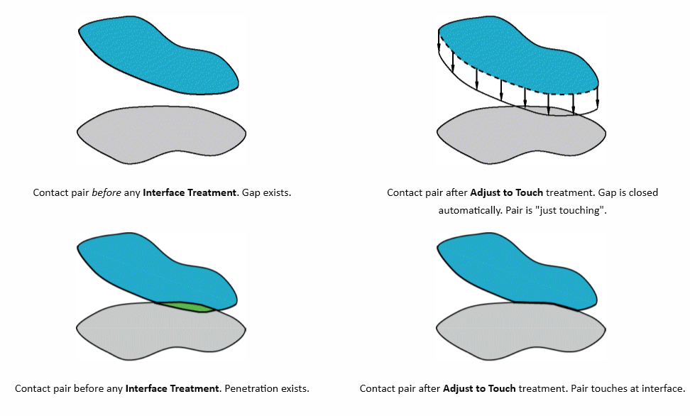
Adjust to touch: Any initial gaps are closed and any initial penetration is ignored creating an initial stress free state. Contact pairs are “just touching” as illustrated.

This setting is useful to make sure initial contact occurs even if any gaps are present (as long as they are within the pinball region). Without using this setting, the bodies may fly apart if any initial gaps exist. Although any initial gaps are ignored, gaps can still form during loading for the nonlinear contact types.
Note:
- The Adjust to Touch option does not lead to uniform contact between concentric cylinders that contain a small initial gap. For this situation, manually specify the gap as an offset in with the Add Offset option.
- Gaps may still be present if the contact pair has regions of differing gaps. When gaps exist, this setting makes sure that initial contact occurs by closing the smallest gap.
Offset: This is a value measured in units of distance and has to do with the minimum distance between the nodes of a contact pair.
For a contact pair with an initial gap, a positive offset will tend to reduce the gap and a negative value will have the effect of increasing it.
For a contact pair with initial penetration, a positive value will reduce penetration.

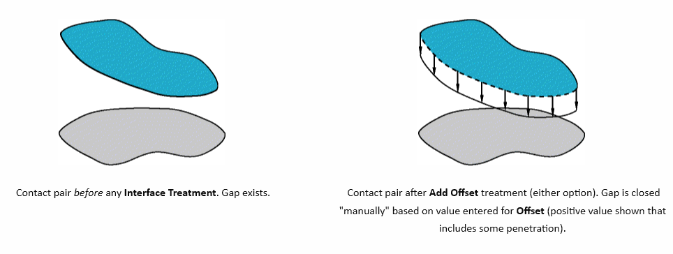
Add Offset : This setting models the true (geometric) gap/penetration and adds in any user defined offset value. For example if a 0.10 mm geometric penetration exists, an offset of 0 mm implies that the contact and target surfaces will be appropriately displaced (to resolve the penetration) to be face to face (zero gap). Such behavior would represent an interference fit.
Offset Only: Using this setting the solver ignores any initial geometric penetrations if the initial contact status is in contact (closed). If the initial status is near field (open), the application ignores the calculated initial penetration (Offset plus geometric gap), and applies only the remaining Offset value (remaining from Offset plus geometric gap calculation).
Offset Only, Ignore Initial Status: This option is the same as Offset only except that this option ignores any initial geometric penetration or gap when calculating contact regardless of the initial contact status, before applying a uniform offset.
Ramping: This means that the offset will be applied linearly over all sub steps of the load step. This is especially useful when non-linearities are present in the model such as in challenging interference fit problem. Without ramping, the entire offset is applied in the first sub-set of the load step.
