Introduction
We discussed time and time steps as they apply to static analysis in a recent article (What is time in static structural analysis? – Time Step vs Load Step vs Sub-Step). In this post, we will take the concept of time further and discuss various aspects of time stepping, or time step optimization.
Step Controls
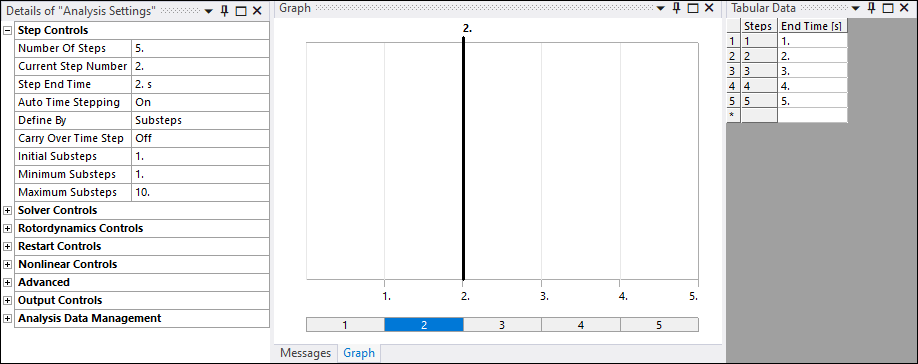
The step controls menu is available under “Analysis Settings” in ANSYS Mechanical.
Number of Steps
You can use this property to specify multiple load steps (or time steps) for the analysis
Current Step Number
This shows which step number is currently selected. The settings of the Step Controls, Nonlinear Controls, and Output Controls apply to this current step number. For a multi step analysis, the current step number is highlighted in the graph as shown below. You can select multiple steps using [shift] and [ctrl] keys.

Step End Time
This is measured in seconds and shows the ending time for the current step. Note that for static structural analysis, time is not physical time. You can read more on this topic here: What is time in static structural analysis? – Time Step vs Load Step vs Sub-Step.
Automatic Time Stepping
ANSYS Mechanical User guide dedicates a section to automatic time stepping. Below is an excerpt from this section.
Auto time stepping, also known as time step optimization, aims to reduce the solution time especially for nonlinear and/or transient dynamic problems by adjusting the amount of load increment. If nonlinearities are present, automatic time stepping gives the added advantage of incrementing the loads appropriately and retreating to the previous converged solution (bisection) if convergence is not obtained. The amount of load increment is based on several criteria including the response frequency of the structure and the degree of nonlinearities in the analysis.
The load increment within a step is controlled by the auto time stepping procedure within limits set by you. You have the option to specify the maximum, minimum and initial load increments. The solution will start with the “initial” increment but then the automatic procedure can vary further increments within the range prescribed by the minimum and maximum values.
Program Controlled:
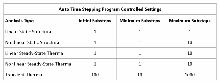
When automatic time stepping is set to program controlled, the Mechanical application automatically switches time stepping on and off as needed. A check is performed on non-convergent patterns. The physics of the simulation is also taken into account. The Program Controlled settings are presented in the following table:

On:
When set to on, the user is able to control some aspects of the automatic time stepping. Time stepping is still automatic but is guided by the user by specifying the initial, minimum and maximum load increment.
Off:
Time stepping is not enabled. You are prompted to enter the Number Of Substeps. The default is 1.
Define By
This displays when you set the Auto Time Stepping property to On or Off. Its drop-down menu contains the options Time and Substep. The default setting for this property depends upon the analysis type. If Time is selected you are able to select the initial, maximum and minimum time increments. If Substep is selected you can select the initial, maximum and minimum substeps.
Carry over Time Step
This property is available when you specify multiple steps. This is useful when you do not want any abrupt changes in the load increments between steps. When this is set to On, the Initial time step size of a step will be equal to the last time step size of the previous step.
Initial Substeps
Specifies the size of the first substep. The default is 1.
Minimum Substeps
Specifies the minimum number of substeps to be taken (that is, the maximum time step size). The default is 1.
Maximum Substeps
Specifies the maximum number of substeps to be taken (that is, the minimum time step size). The default is 10.
References
ANSYS Mechanical User Guide
