Introduction
In a recent article we had explored time stepping options which are part of the Analysis settings in ANSYS workbench – Time Stepping in Ansys.
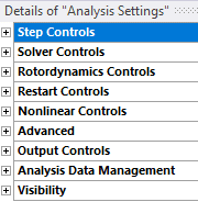
In this article we will take a look at the Solver Controls settings which is the second option under Analysis settings.

Solver Controls
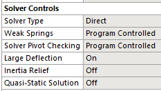
When expanded, the solver controls menu provides the following properties.

Solver Type
The two options for the solver type are Direct and Iterative.
Before we discuss the two solver types, it is beneficial to define the term equilibrium iteration.
- In a linear analysis, the stiffness matrix [K] is calculated only once
- The matrix equation {F} = [K]{U} is solved only once
- In a non-linear analysis the stiffness matrix is evaluated multiple times
- Each evaluation of the stiffness matrix constitutes an equilibrium iteration
The direct solver used in Ansys is the Sparse Direct Solver. The Sparse Direct Solver makes use of the fact that the finite element matrices are normally sparsely populated (many zero terms). This sparsity allows the system of simultaneous equations to be solved efficiently by minimizing the operation counts. In a direct solver, there is one matrix solver iteration per equilibrium iteration.
ANSYS offers a large number of iterative solvers as alternatives to the direct solvers . These alternatives in many cases can result in less I/O or disk usage, less total elapsed time, and more scalable parallel performance (on multi-core systems). However, in general, iterative solvers are not as robust as the direct solvers. For numerical challenges such as a nearly-singular matrix (matrix with small pivots) or a matrix that includes Lagrangian multipliers (Normal Lagrange contact types), the direct solver is more effective than the iterative solver.
Detailed information on direct and iterative solvers as used in ANSYS can be found here: https://www.mm.bme.hu/~gyebro/files/ans_help_v182/ans_thry/thy_tool8.html
Also read: Understanding Solver Types and Force Convergence Plots in ANSYS
Weak Springs
This topic has been covered in a separate article – Weak Springs, Yes or No?
Solver Pivot Checking
This setting allows the user to define how solver pivots shall be treated. There is a dedicated article talking about the concept of pivot and its treatment – ANSYS Solver Pivot Warnings – What are they and what to do about them?
Large Deflection
Large-deflection effects are categorized as either large deflection (or large rotation) or large strain, depending on the element type. These are listed (if available) under Special Features in the input data table for each element in the Element Reference.
When large deflection effects are included (NLGEOM,ON), stress stiffening effects are also included automatically. Large deflection and stress stiffening effects are collectively referred to as Non-Linear Geometry effects (When to run Non-Linear FEA?)
When large deflection is turned off, the solver generates the stiffness matrix once, corresponding to the initial geometry.
For a large deflection analysis, the stiffness matrix is computed for each equilibrium iteration. For accurate results, large deflections should be activated if material plasticity is to be modeled and/or the geometry is expected to deform significantly with the application of loads (such as a fishing rod being stretched).
Inertial Relief
When the Inertial Relief feature is activated (IRLF, 1) the program calculates accelerations to counterbalance the applied loads (inertia relief).
Displacement constraints in a model should be only those necessary to prevent rigid-body motions (3 are needed for a 2D structure and 6 for a 3D structure).
If the minimum number of displacement constraints are applied and it is a linear static analysis, the sum of the reaction forces at the constrained points will be zero. However, if it is a nonlinear static analysis , the sum of reaction forces at the constrained points will be approximately zero due to the error introduced by nonlinear iterations. This is where inertial relief can be beneficial. Here is an article by Simutech Group discussing inertial relief in detail : Static Analysis with Inertial Relief.
Quasi-Static Solution
The options for this property include On and Off (default). For analyses that are quasi-static in nature, and that fail to converge, you can set this property to On in order to achieve convergence.
Quasi-static implies a condition where we can consider a problem as static at a specific moment in time. The key assumption is that the applied load occurs extremely slowly, with a frequency much lower than that of the structure. As a result, the inertial effects are negligible. This assumption is valid when inertia effects are minimal, and it also aids in simplifying nonlinear problems into linear systems.
A mechanism modeled via a static structural analysis could be considered a quasi static system.
