INTRODUCTION
Joints can be an efficient way to model interaction between bodies. In structural analyses they can be especially useful when simulating mechanisms. The relative degrees of freedom between two bodies can be explicitly defined to achieve a vast array of joint configurations. One such configuration is the revolute joint. In this article, we will discuss some aspects of modeling a revolute joint and list some best practices.
Revolute Joint
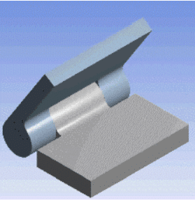
A revolute joint allows one relative rotation between two bodies, constrains all three relative translations, as well as the other two relative rotations. It is often utilized to model cylinder – pin assemblies (Hinge) or assemblies with linkages that behave like pendulums.
Revolute Joint Limitations and Best Practices
Sometimes a joint modeled in ANSYS does not behave as expected by the user. There could be multiple reasons for this. When debugging a revolute joint one may consider the following factors and limitations :
- Use appropriate coordinate system
The degree of freedom constraints are defined in a local coordinate system. The local coordinate system must be specified such that the revolute axis is coincident with the axis of rotation. A single coordinate system can be used to define multiple joints, as long as the revolute axis is coincident (being parallel to the revolute axis is not enough). If the coordinate system is not appropriately defined, unexpected rotations may be observed. - Turn on Large Displacements (Non-Linear Geometry)
This should be done for any joint (not just revolute joints). If you run a structural analysis with large displacements turned off, you would get the following warning message via ANSYS output:
Joints are being used in the current analysis with Large Deflection turned off. Thus, only linearized joint behaviour will be considered. If a finite rotation and large deflection effects are to be considered, please turn on Large Deflection.
Revolute joints are especially sensitive to large displacement effects. A model with revolute joints defined may display very strange behavior (such as the cylinder expanding relative to the pin, instead of rotating around it), or may not converge at all to a solution. - Do not define boundary conditions on constrained surfaces
A revolute joint specifies constraints in all DOF. Any additional boundary conditions defined on the mobile or reference surfaces will cause over constraint of the nodes and the solver may halt with an error message. - Consider Joint Parameters
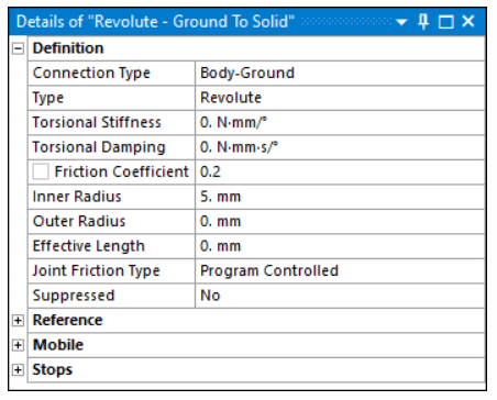
A revolute joint does not inherently provide a limit to the rotational degree of freedom in the axis of rotation. This means that the rotating body can rotate indefinitely, potentially resulting in convergence difficulties. There are multiple ways to accomplish this, some of which include defining several joint parameters which can be seen in the image below.
- Torsional Stiffness
The Torsional Stiffness property defines the measure of the resistance of a shaft to an applied torque. - Torsional Damping
The Torsional Damping property defines the measure of resistance to the angular vibration to a shaft or body along its axis of rotation. - Joint Friction
The Joint friction introduces a resisting friction torque. In order to compute this torque, the revolute joint is assumed to be a cylinder pin assembly (even if it isn’t physically). The cylinder is characterized by its inner radius, outer radius, and an effective length as shown in the image below.
- Torsional Stiffness
- Consider additional constraints
- Stops and Locks
Stops and Locks are optional constraints that may be applied to restrict the rotation of revolute joint (though stops and locks may be defined for several supported joint types).
- Stop: A Stop is a computationally efficient abstraction of a real contact, which simplifies geometry calculations. For Stops, a shock occurs when a joint reaches the limit of the relative motion.
- Lock: A Lock is the same as a Stop except that when the Lock reaches the specified limit for a degree of freedom the Lock becomes fixed in place.
- When using the Mechanical APDL solver, Stops and Locks are active only when Large Deflection is set to On. This is because Stops and Locks make sense only in the context of finite deformation/rotation. If Large Deflection is Off, all calculations are carried out in the original configuration and the configuration is never updated, preventing the activation of the Stops and Locks.
- It is important to apply sensible Stop and Lock values to ensure that the initial geometry configuration does not violate the applied stop/lock limits. Also, applying conflicting boundary conditions on the same DOF leads to non-physical results and therefore is not supported.
- If both stops and locks are specified, then lock specification takes precedence. That is, if the degree of freedom is locked at a given value, then it will remain locked for the rest of the analysis.
Besides stops and locks, other constraints may also be considered. For example, the nodes on the OD of a cylinder may be coupled in rotation along the revolute axis. In some situations this could aid in obtaining the expected joint behavior.
- Stops and Locks
References
1- MPC184 – Revolute Element, ANSYS Help Documentation
2- Joint Friction – ANSYS Help Documentation
3- Joint Properties – ANSYS Help Documentation
4- Joint Stop and Locks – ANSYS Help Documentation
