What are Remote Points ?
Remote Points are points represented by a single node called “Pilot node” scoped to (“linked” to) a geometry at an arbitrary location in space. The pilot node has six degrees of freedom and can be used to approximate the behavior and kinematics of the scoped geometry. They can be scope to a vertex, edge, face, body, node, or element face.
Remote Points are typically utilized in conjunction with remote boundary conditions and remote loads in order to model physical phenomena and behaviors and simplify various aspects of the model.
What are the advantages of Remote Points ?
The main purpose of remote points is to define remote boundary conditions such as a remote force or a remote displacement. But why would you want to do that? There are several reasons for this, some of which are listed below:
- Abstracting a connection to a solid model
By “abstracting a connection” we imply modeling physical phenomena without having to model the complete geometry associated with the phenomena. This can greatly simplify the model by reducing the geometry modeling, meshing and solution run time. Some example of this are:- Representing a body by a point mass (Also see: Point Mass vs Remote Force)
- Modeling joints ( Also see: Revolute Joints)
- Replacing a rigid body not of interest with a remote displacement
- Gaining control over the degrees of freedom of a geometry
A remote point has six degrees of freedom (three translations and three rotations). This means that you get access to degrees of freedom (DOF) which may not be inherently available with the element types used. For example, a solid element has 3 degrees of freedom (Translations). A remote point can be used to apply a rotation to the body which is not possible otherwise.
How are remote points defined in Ansys Mechanical ?
There are two ways of defining remote points :
- Remote Point Object
Right click on Model, go to Insert and then select Remote Point
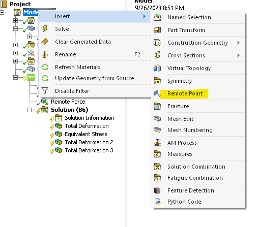
You can select the appropriate options from “Details of Remote Point” to define the remote point in space.
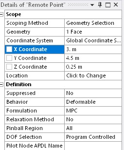
Once you have the remote point, you can scope a remote boundary condition to it such as a remote displacement or a remote force. You can apply multiple boundary conditions to the same remote point.
This brings us to the second method of defining remote points, which is via the remote boundary condition.
- Remote Boundary Condition
You do not have to manually create a remote point in order to apply a remote boundary condition. If you right click on the analysis branch within Mechanical (for example “Static Structural), go to insert and you will see options to add a remote force and remote displacement. If you select these, Ansys will automatically create “internal” remote points to scope the boundary conditions to. Each remote boundary condition is associated with its own “behind the scenes” remote point. The following boundary conditions make use of remote points:- Point Mass
- Thermal Point Mass
- Joints
- Spring
- Bearing
- Beam Connection
- Remote Force
- Moment
- Remote Displacement
How are remote points connected to the scoped geometry?
The mechanism used to connect remote points to the scoped geometry is Multi Point Constraint (MPC) Equations. These equations are used to constrain the nodes on the scoped geometry with the pilot node. Here is a video by Ansys explaining how MPC equations work (at 3:38).
Remote Point Test Case
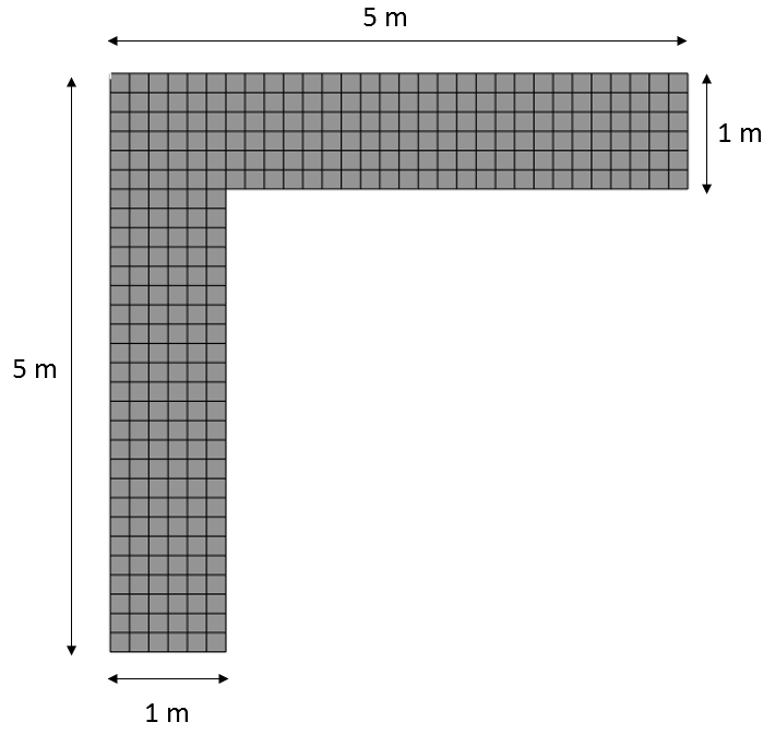
The best way to explore the capabilities of remote points is through an example. Figure 3 shows a simple meshed geometry. The Ansys default structural steel material properties are utilized for this model.
The base of the structure is fixed and a 500 kN force is scoped to the face as shown in Figure 4. This force could represent a mass attached to the face.
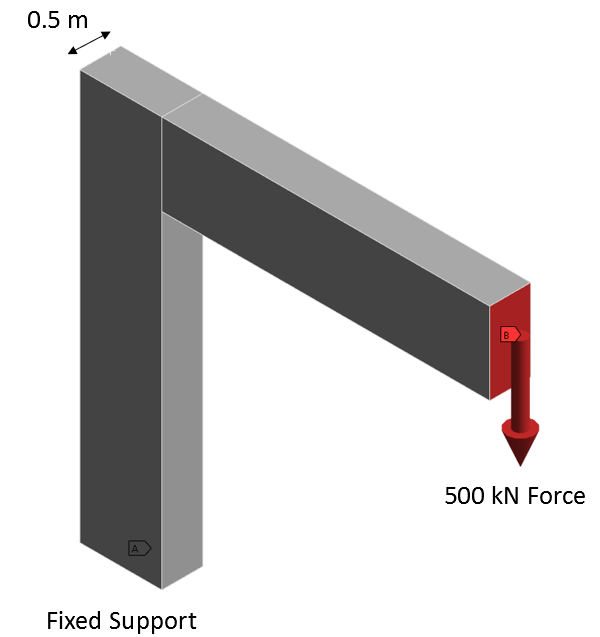
Figure 5 shows the resulting deformation at 50X magnification.
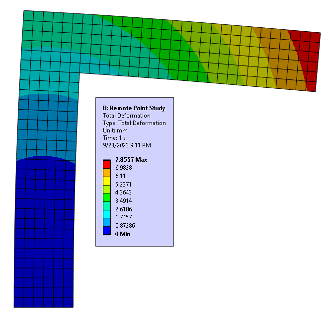
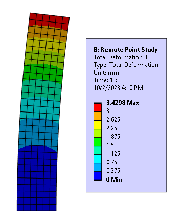
Figure 6 shows the displacement of the vertical portion of the geometry (at X 100 deformation scale). The reason for showing this will become clear later in this article.
Using a remote point (remote force)
We could use remote points to simplify this geometry by eliminating the horizontal portion of the structure. There could be several reasons for doing this, but the most common reason is to save on meshing and run time (by having fewer nodes and DOF in the model). Let us see how this works.
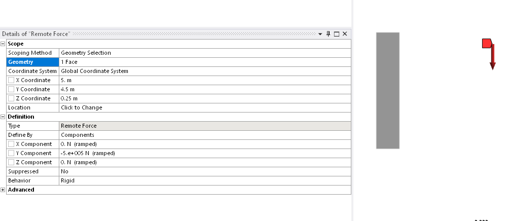
You can right click on Static Structural, click on insert and then select remote force. With scoping method set to geometry selection, you can click on the green face shown below. It helps if you have a selectable face to scope the remote force or point too. In this instance the face represents the interface between the vertical and horizontal portions of the geometry.

Use the coordinates to make sure that the force is located at the original location i.e. 5m away from the surface.
Below is an image showing the total deformation result. It can be seen that the result is very close to what was reported with the original geometry (Figure 6).
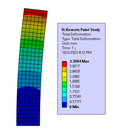
We were successful in modeling the behavior of the original model using an appropriate remote force:
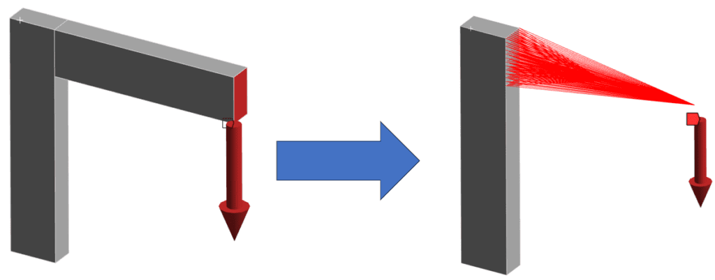
Remote Force Behavior : Rigid vs Deformable vs Coupled vs Beam
When you create a remote force you have the option to specify its behavior. The options are Rigid, Deformable, Couple and Beam.
Rigid Behavior: All nodes in the scoped geometry have zero relative displacement to each other. This option is useful when the geometry that is being represented by the constraint equations significantly stiffens the model at the point of attachment. This option is commonly used.
Deformable Behavior: The scoped geometry is free to deform. This is a general purpose behavior where the points of attachment are allowed to deform. The stiffening affect from the abstracted geometry is not considered. This behavior option is commonly used.
Coupled: The scoped nodes have the same DOF solution as the remote point location. This is useful when you want a portion of geometry to share the same DOF solution (such as UX) that may or may not be known. In practical applications this behavior is rarely used but may be employed for specific scenarios such as those involving design optimizations.
Beam: This option connects the remote point to the scoped nodes by means of linear massless beam elements (BEAM188). The material and radius of the beam have to be defined. However, the material does not include the material properties for the Coefficient of Linear Thermal Expansion. As a result, this may develop thermal differential strains when thermal conditions are applied to the model. To address this issue, Line Bodies with appropriate material properties can be used instead of a Remote Point
References
