INTRODUCTION
One of the most important phases of running an engineering simulation is the pre-processing stage. Pre-processing refers to setting up a geometry to make it “analysis ready”. A “dirty” geometry can cause issues with meshing and / or contact setting while wasting precious time and resources. Various CAD software provide tools that can be used to “repair”, or “clean up” geometries prior to meshing. Design modeler, one of the native CAD tools in Ansys workbench offers several features in this regard. In this article, we will take a brief look at these features and how they can be utilized to create clean and efficient geometries.
Repair in Ansys Design Modeler
The repair menu can be accessed from Tools. The image below shows the repair options available.
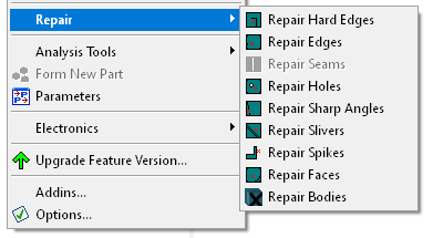
These are a set of tools that allow you to easily search and fix unwanted geometries, geometric features or errors, also referred to as faults, from the model.
We will now discuss what each of these features refer to.
The content below has been derived from Ansys Design Modeler Help Documentation [1].
Repair Hard Edges
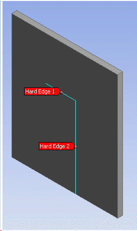
Hard edges are edges which do not take part in defining the boundary of a face. Hard edges are undesirable because they can results in an unnecessarily fine mesh around them. The figure below shows an example of a couple of hard edges on a plate. Using the “Edge Delete” option you can get rid of these hard edges.
Repair Edges
Edges are just as the name implies – you can identify any edge in a model and attempt to perform an operation on it. Design Modeler uses the edge length as the criteria to search for short edges in the model. An edge whose length lies between the minimum and maximum limit is determined to be a fault. There are several methods available to repair the edges:
- Vertex Connect: The two vertices of the short edge will be fused into one vertex and the edge will be deleted. The fused vertex will be at the mid point of the edge.
- Edge Merge: The short edge will be merged with one or more adjacent edges. Ansys DesignModeler automatically suggests one adjacent edge for merging. You can change this selection if required. However, an edge needs to be specified for the operation to be successful.
- Edge Delete: The short edge will be deleted using the Edge Delete method. Any gaps left behind by the delete operation are healed by growing adjacent edges.
- Face Merge: The short edge will be fixed by merging a set of faces with the Face Merge method. If this method is chosen, you need to select the faces to merge. Note, while manually selecting faces for the face merge operation, you can select only those faces that use the vertices of the short edge or the short edge itself.
Repair Seams
You can use this repair feature for surface bodies only. Ansys Design Modeler generally defines a seam as a set of connected laminar edges separated along their length by small gap. A typical seam is shown below.
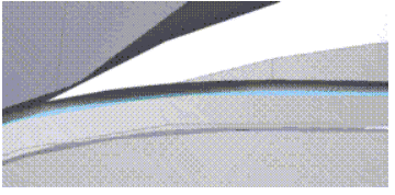
Design Modeler uses the maximum width of gap along length between connected laminar edges as the criteria to search for seams in the model. The set of connected laminar edges whose maximum width lies between the minimum and maximum limit is determined to be a fault.
There are two methods available for Seam repair:
- Automatic: If all the edges belong to one face then Edge Delete method is used to fix the fault. In this approach, edges that form the seam will be deleted and the gaps will be closed by extending the surface. Otherwise, Edge Connect method is used.
Repair Holes
This feature can be used to remove holes from a surface or a solid body. There are several methods available for hole repair:
For Holes on Surface Bodies:
- Edge Delete: The edge or edges that form the hole will be deleted and the gaps
will be closed by extending the surface. - Surface Patch: The Surface is patched using the Surface Patch method to cover the
hole. The edges that form the hole remain. - Edge Connect: The edges that form the hole will be connected.
For Holes on Solid Bodies:
- Fill Hole: The opening is first closed with the Surface Patch method and the inner
volume is filled using the Fill By Caps method. If successful, the edges of the hole
may sometimes not be present in the final result.
Repair Sharp Angles
Sharp angles refer to edges that form very small angles.
Design Modeler uses the interior angle formed by connected edge pair of the face as the criteria to search for sharp angles in the model. A connected edge pair whose interior angle lies between the minimum and maximum limit is determined to be a fault. Below is an example of a sharp angle:
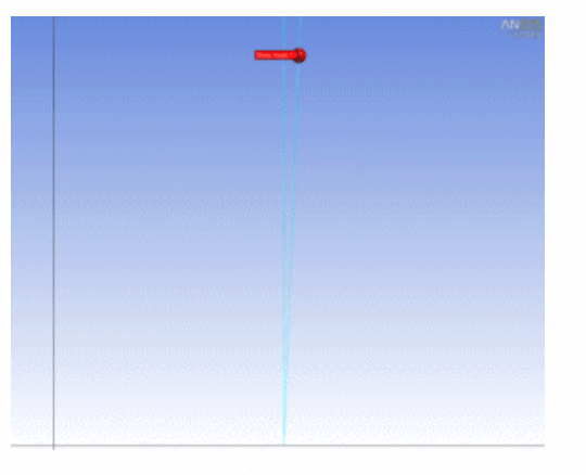
Face Merge: The sharp angle face will be merged with one or more adjacent faces, so that overall angle increases. Ansys Design Modeler automatically suggests one adjacent face for merging. You can change this selection if required. However, a face needs to be specified for the operation to be successful. Note, while manually selecting faces for the face merge operation, you can select only those faces that use the vertices of the face or the adjacent to the face.
Repair Slivers
A sliver is a narrow face having two or more edges. Design Modeler uses the maximum width of the narrow region as a criteria to search for sliver faces in the model. Several methods can be used to get rid of slivers:
- Automatic: A Face Merge method is used to fix the fault. The sliver face is merged with one of the adjacent faces. If this method fails, an alternative approach is used. If the alternative also fails then the Face Delete method is attempted. In this approach, the sliver face will be deleted using the Face Delete method. Any gaps left behind by the delete operation are healed by growing adjacent faces.
If this method fails then Edge Connect method is attempted. In this approach, the sliver face will be deleted and the gaps left behind are healed by connecting sliver face edge. - Face Merge: The sliver face will be merged with one or more adjacent faces. Ansys Design Modeler automatically suggests one adjacent face for merging. You can change this selection if required. However, a face needs to be specified for the operation to be successful. Note, while manually selecting faces for the face merge operation, you can select only those faces that use the vertices of the face or the adjacent to the face.
- Edge Connect: In this approach, the sliver face will be deleted and the gaps left behind are healed by connecting sliver face edge.
Repair Spikes
A spike is basically what the name suggests – It is a spike in a polygon. It is a small part of the geometry which protrudes outward similar to what is shown below:
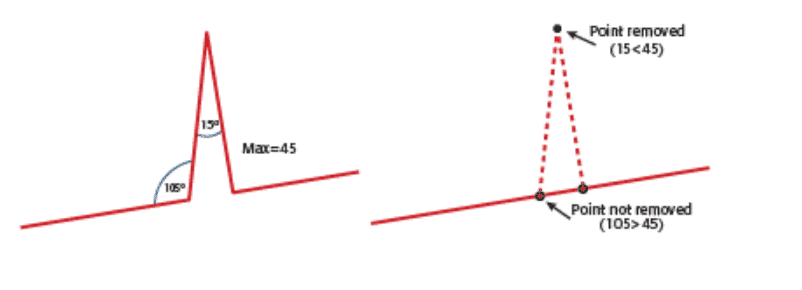
Design Modeler uses the maximum width of the narrow region of the face edge set as the criteria to search for spikes in the model. The edge set whose maximum width lies between the minimum and maximum limit is determined to be a fault.
- Automatic: First, a Face Merge method is used to fix the fault. The narrow region of spike face is chopped and merged with one of the adjacent faces. If this method fails, an alternative approach is used to fix the chopped face. If this method also fails and the body is a Surface body then the Edge Delete method is attempted. In this approach, the narrow edges of spike face will be deleted using the Edge Delete method.
Repair Faces
You can use this feature to remove small faces from the model. Design Modeler uses the area of the face as the criteria to search for small faces in the model. A face whose area lies between the minimum and maximum limit is determined to be a fault. If all faces of a body are chosen as faults, then the entire body will be deleted.
- Automatic: First, a Face Merge method is used to fix the fault. The small face is merged with one of the adjacent faces. If this method fails, an alternative approach is used to fix the small face.
- Face Merge: The small face will be merged with one or more adjacent faces. Ansys Design Modeler automatically suggests one adjacent face for merging. You can change this selection if required. However, a face needs to be specified for the operation to be successful. Note, while manually selecting faces for the face merge operation, you can select only those faces that use the vertices of the face or the adjacent to the face.
Repair Bodies
This feature can be used to remove small bodies within an assembly. This can be especially useful when trying to remove components such as nuts, bolts and washers.
As a first step, you must select the Body Type to be repaired as shown in the Details View below:

Based on Repair Body Type selected in the Details View, Design Modeler uses the respective body property as the criteria to search for small bodies in the model. Body properties for three body types are shown below.
| Body Type | Body Property |
| Solid | Volume |
| Surface | Area (Cumulative Face Area) |
| Line | Length (Cumulative Edge Length) |
Body Delete: The small bodies satisfied with the criteria will be deleted from the model.
References
[1] Ansys Design Modeler Repair
[2] https://docs.safe.com/fme/html/FME-Form-Documentation/FME-Transformers/Transformers/spikeremover.htm
