Introduction
When we talk about engineering numerical simulation (FEA / CFD) we often ascribe short descriptive titles to the models that we are working with. Sometimes these terms may be used loosely – they could mean different things depending on the project and the context. Other times, the terms may have specific well-defined meanings. Not understanding the correct terminology can lead to miscommunication at the workplace.
In this article we will briefly discuss some terminology which can come in handy, especially for engineers who are less experienced or not familiar with engineering modeling.
Words (and prefixes) such as global, local, full, and Sub usually refer to the geometry that is being analyzed but sometimes also have load implications.
Global Model
The global model is typically a “top level” model. The word “global” is relative to “local”, and may refer to the “full model” as opposed to a smaller, isolated model. Often times, the global model includes an assembly model from which the local / Sub-Models are derived. Information from the results of a global analysis (such as load reactions, displacements) may be used as reference points or inputs for other smaller scale analyses. Many times the global model includes a large geometry but the overall modeling is simplified.
Local Model
A local model is relative to a “global model”. It may refer to the model of a sub-assembly or a component as opposed to a larger assembly. Information from the global model may be utilized for the local model.
The most common reason to build a local model is to study the behavior of a region of the geometry in more detail – A local model typically includes a smaller geometry, but the modeling may be more sophisticated and detailed.
A local model could be used for geometry optimizations via parametric studies (for example to determine the desirable thickness of a plate), load optimizations (for example to establish the preload to be applied to a bolt) or provide more accurate results (such as the maximum stress on a radius).
A local model can help us refine a model in ways which may not have been possible with the global model due to computing or time resources.
A local model:
- may be used to study an isolated region of the geometry (such as a clamp within an assembly)
- have several features of the geometry modeled in detail (such as fillets, radii, chamfers etc.)
- consist of a more refined mesh (for example for a mesh independence study)
- include more accurate contact definitions (for example frictional contact vs bonded contact)
- model additional loads (such as bolt preload)
- model specific phenomena in more detail (such as the plastic response of a structure before failure)
- may be used for debugging purposes (such as resolving numerical convergence issues)
The above list is not exhaustive. There could be other reasons for local modeling depending on the objectives of the analyst. Local models are useful because they can achieve the above (and more) in a way that is manageable from a time and resource standpoint.
Submodeling
A lot of people (especially engineers who are not analysts) use the terms Sub-Model and Local Model interchangeably. This is incorrect!
A local model is a general term for a model that includes an isolated geometry.
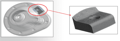
Submodeling on the other hand refers to a specific modeling technique typically used to study the effect of a refining the mesh on a portion of the geometry. It is based on Saint Venant’s Principle which states that:
The stresses on a boundary reasonably distant from an applied load are not significantly altered if this load is changed to a statically equivalent load. [1]
This implies that you may cut a portion of the global model, refine the mesh, and run analysis only for the selected portion provided that displacements are properly specified at the cut boundaries. If displacement results from the parent study (global model) are accurate, then these displacements are considered as boundary conditions at the cut boundaries for the submodeling study.
The boundaries of the submodel must be sufficiently far from stress concentration areas. Additionally, note the term “reasonably distant” as stated under Saint Venant’s Principle.
Geometric cuts that are made “too close” to the area of interest may invalidate the study because the underlying assumption that mesh refinement of the submodel does not impact displacements.
You can find more detail on Submodeling in this Ansys training presentation : Submodeling Technique
References
[1] SolidWorks Help
