Introduction
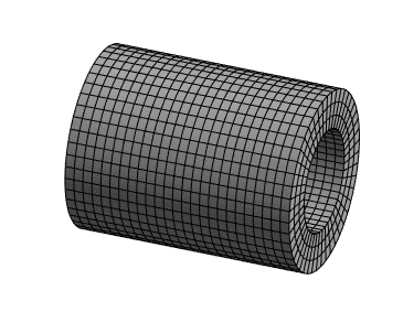
Sweep mesh is one of the mesh methods available within Ansys Workbench. A sweep mesh is desirable because it is a structured mesh as opposed to an unstructured mesh (Read more: Structured vs Unstructured mesh).
We have discussed the basis of the sweep mesh in an another article (Ansys Mesh Methods Explained). We touched upon what a sweep mesh is but did not delve into its details. Below you will find an excerpt from the linked article, followed by a detailed discussion on the meshing features and options related to sweep mesh.
What is a Sweep Mesh?
A sweep mesh generates a mesh on one surface (source face) of a body and literally “sweeps” along the length of the body up to another surface (target face). The mesh pattern is identical along the length of the body.
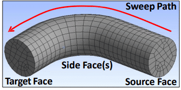
The user can control the number of mesh divisions along the sweep path.
A swept mesh requires that the body is “sweepable” – The source and target meshes must be topologically identical. Additionally, the cross section of the part must be free of features that will “interrupt” the sweeping of the mesh (If you have features such as holes or grooves along the length then a sweep mesh cannot be generated).
Hex / wedge elements may be created with the sweep mesh. As one can see, for clean geometries the sweep mesh has potential of creating highly efficient meshes.
Sweep Mesh Settings
The image below shows the sweep mesh settings available within Ansys Workbench:
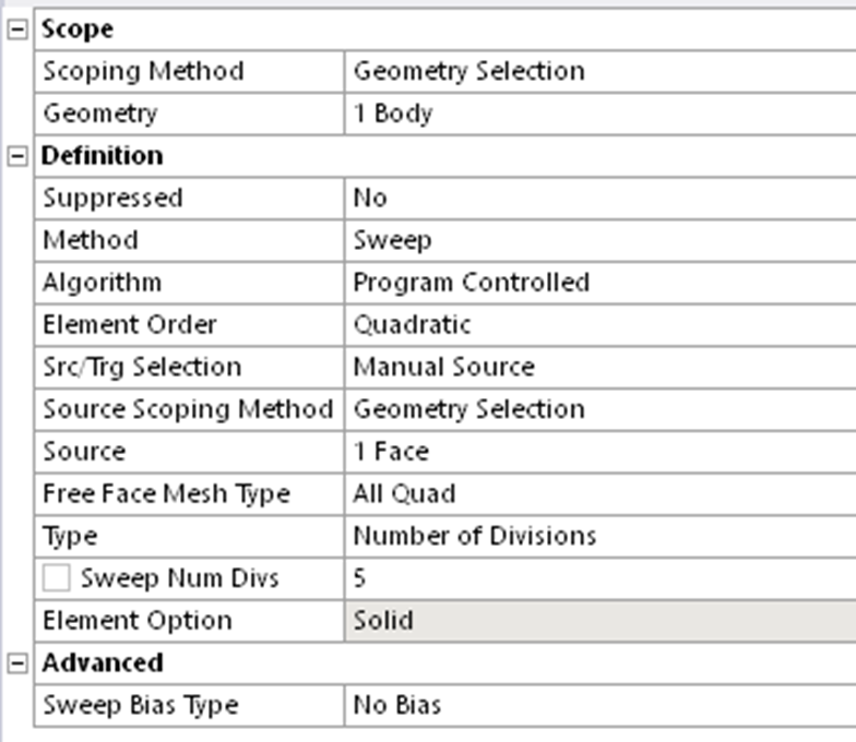
Let us look at what each of these settings refers to. The first four settings (Scoping Method to Method) are self explanatory.
Algorithm
The two options available here are Program Controlled and Axisymmetric
Program controlled algorithm can only be applied to the traditional sweepable models. This option does not support Mesh based Defeaturing.
Axisymmetric algorithm can be applied to all axisymmetric models. An axisymmetric geometry is such that it looks the same if you rotate it about an axis (such as a cylinder).
Axisymmetric Sweeper does not support shared topology. It supports Contact Sizing, Topology Protection and Mesh based Defeaturing.
Element Order
You can select Linear, Quadratic or the Global Setting (Read More: Linear vs Quadratic Elements).
Src/Trg Selection
This is the option for the selection of the source and target for the sweep mesh. The mesh will be “swept” from the source face to the target face as shown in Figure 1. The following choices are available.
- Automatic: The program determines the best source and target for the body.
- Manual Source:
- You select the source and the program determines the target.
- Useful when there are multiple source target pairs and you want to specify the source in order to get the correct bias through the sweep direction (Refer to Figure 3 – Figure 5).
- Another application is when your cross section is changing and the mesh quality would be better when sweeping from one side vs. another.
- Manual Source and Target:
- The sweeper will revolve the mesh around common edges/vertices.
- Useful when you want to sweep a body where the source and target faces share vertices and/or edges.
- Automatic Thin:
- This choice is for thin models and thin sheet metal parts, or any application where you want one hex or wedge through the thickness, in preparation for using the Mechanical APDL application’s SOLSH190 (Solid Shell) element or the LS-DYNA thick shell element. (Read more: Solid vs Shell vs Solid Shell Elements )
- The face with the largest face area is selected as the primary source and the algorithm determines the rest of the source faces.
- For multibody parts, only one division through the thickness is possible.
- For single body parts, you can define multiple elements through the thickness.
- Manual Thin:
- The same restrictions apply as described above for Automatic Thin. However, with this choice, you can do any of the following:
- Pick one source face and allow the program to determine the rest.
- Pick all of the source faces and allow the program to do nothing but mesh the source faces and sweep them to the target.
- Pick multiple source faces and mesh one target face.
- The same restrictions apply as described above for Automatic Thin. However, with this choice, you can do any of the following:
Why is Src/Trg Selection Important?
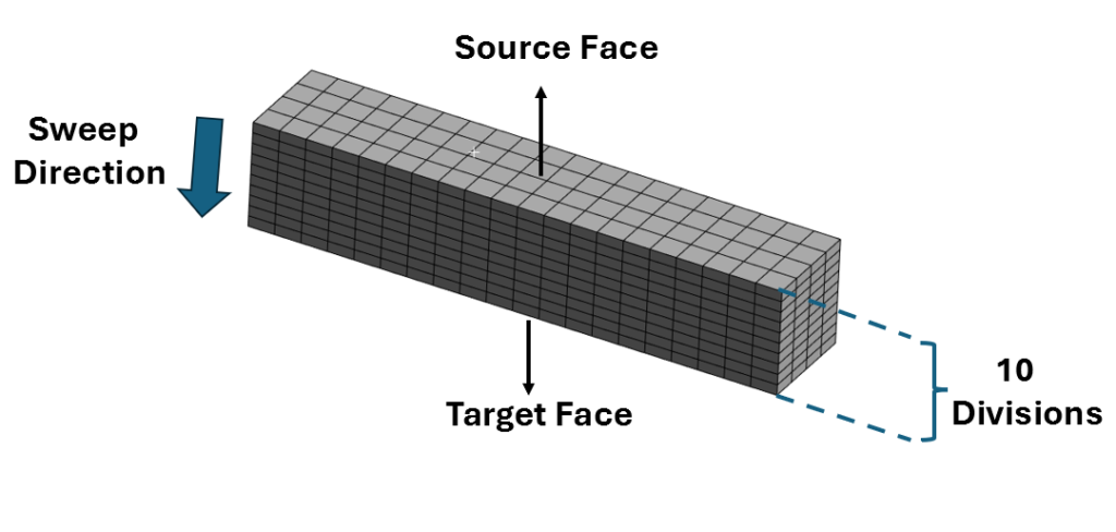
The selection of the source and target faces can have a significant impact on how the mesh is structured. Consider a beam with 10 divisions defined along the sweep direction. Compare the source and target settings in Figure 3 – Figure 5 and the corresponding meshes.
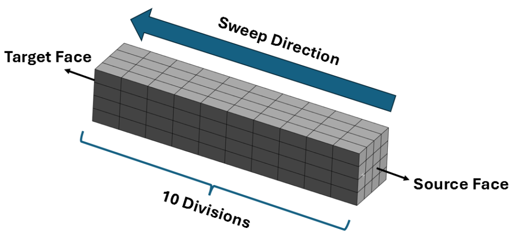
Figure 3 Shows a swept mesh with 10 mesh divisions along the length of the beam. Figure 4 shows the same beam swept along the width with 10 divisions.
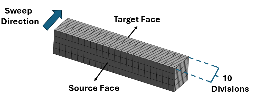
Figure 5 shows the beam swept along its height.
Free Face Mesh Type
This setting determines the shape of the elements used to fill the swept body (pure hex, pure wedge, or a combination of hex/wedge). There are some caveats related to the mesh type:
- If the source face is also a side face of another body, the face will always be quad mapped.
- When set to either Quad/Tri or All Quad and the source face can be mapped meshed, the face will sometimes be mapped meshed even if it means applied sizing controls (such as Contact Sizing, Sphere of Influence, etc.) will be ignored.
- In some cases when Src/Trg Selection is set to Automatic, the source face that is selected by the software must be quad mapped in order for the sweep method to be successful. In these cases, the option that is specified for Free Face Mesh Type may be ignored.
Type
This setting allows you to specify a Number of Divisions or Element Size through the sweep direction. Once again there are several nuances related to this:
- When sweeping generalized bodies that share faces, the Element Size is a soft constraint on interval assignment and the Number of Divisions is a hard constraint. A hard constraint is one that is respected by the mesher and the mesh will fail to generate if the mesher cannot meet the constraint. A soft constraint allows the mesher to modify the restriction that has been imposed.
- If you have conflicting Number of Divisions constraints, the sweeper will fail and yield a message such as: “The number of divisions specified in sweep method is inconsistent with the internal number of divisions in mapped face meshing. Please check the specified parameters” – You may be able to fix this by changing the number of divisions or manually selecting the appropriate source / target faces.
- To obtain a regular mesh in the sweep direction, the guiding edges must have consistent lengths. You can define virtual split edges to achieve consistent lengths for these edges.
User Defined Criteria
This setting only appears when the Src/Trg Selection is set to Automatic Thin. It allows you to select the type of Automatic Thin sweep. The available options are Program Controlled and Protect Internal Edges.
- For Program Controlled, the interior loops in the model are not preserved while performing thin sweep.
- When you select Protect Internal Edges, the interior loops in the model are preserved while performing thin sweep.
Element Option
This option is selectable if the Src/Trg selection is set to Manual Thin or Automatic Thin (and greyed out for other selections). You can instruct the solver to use Solid Shell elements where possible, or to always use a Solid element.
Sweep Bias Type
You can specify the way the mesh is biased along the sweep direction. The available options are as shown below:

When No bias is selected (default) the number of divisions will be evenly spaced along the sweep direction (as shown in Figure 3 – Figure 5). You can select one of the four bias options available and specify a numerical value for the Sweep Bias.
Figure 7 and 8 show meshes with the first Bias option selected and with Sweep Bias values of 5.0 and 10.0 respectively.
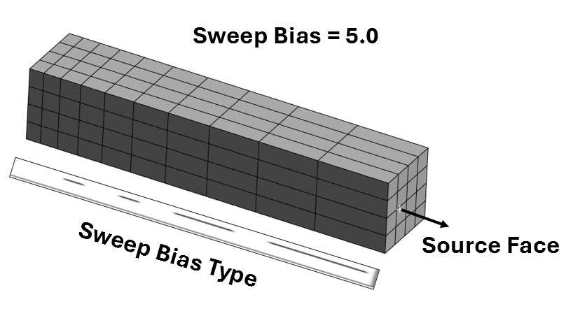
Comparing Figure 6 and Figure 7 you can tell that the higher the bias value the more “pronounced” the bias is. For higher bias values you will tend to get (depending on the bias type selected) regions with wider elements and those with more “bunching” of elements.
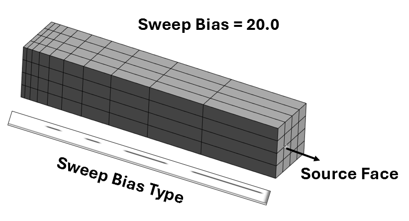
Sweep bias can be a useful tool for efficient mesh refinement.
References
[1] Introduction to ANSYS Meshing, Module 01
[2] Ansys Help Documentation
