Introduction to Contacts in Ansys
In Ansys, a contact is defined by a pair of surfaces referred to as contact and target (selecting contact and target in Ansys). Defining a contact ensures that two bodies do not interpenetrate at these surfaces. The interaction between the bodies is governed by their ability to separate or slide relative to each other.
Types of Contacts in Ansys
Ansys offers five primary types of contacts, each with distinct behaviors:
- Bonded Contact – The contacting surfaces are tied together, preventing both separation and sliding.
- No Separation Contact – Allows frictionless sliding but prevents separation.
- Frictionless Contact – Permits both separation and sliding without resistance (coefficient of friction = 0).
- Rough Contact – Allows separation but no sliding (infinite friction).
- Frictional Contact – Allows both separation and sliding with friction, where the user can define a coefficient of friction.
Among these, frictional contact is often the most realistic representation of real-world interactions. However, bonded contact is the easiest to simulate, leading to its overuse—particularly by inexperienced analysts. This can result in inaccurate predictions, poor designs, and even hazardous situations.
Case Study: Impact of Contact Type on Stress Analysis
To illustrate the importance of selecting the right contact type, let’s examine a simple assembly:
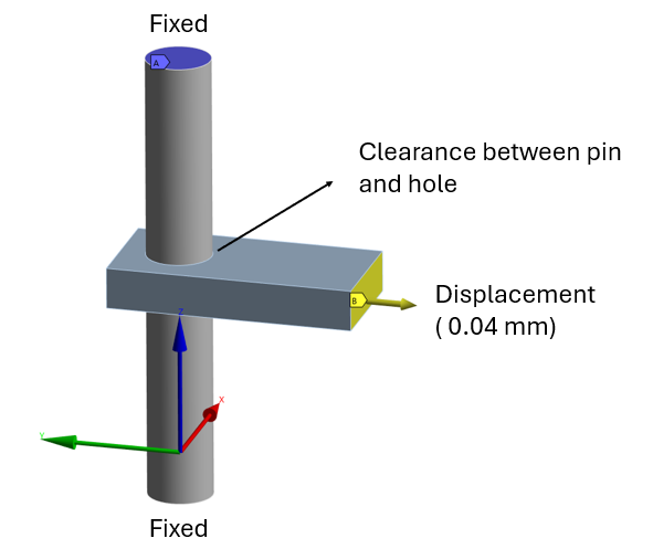
- A rectangular plate with a through hole.
- A pin inserted into the hole with some clearance.
- A small displacement applied to one end of the plate.
- The pin’s ends are fixed in all degrees of freedom.
The objective is to evaluate the stress intensity in the plate behind the pin, ensuring it remains below 100 MPa.
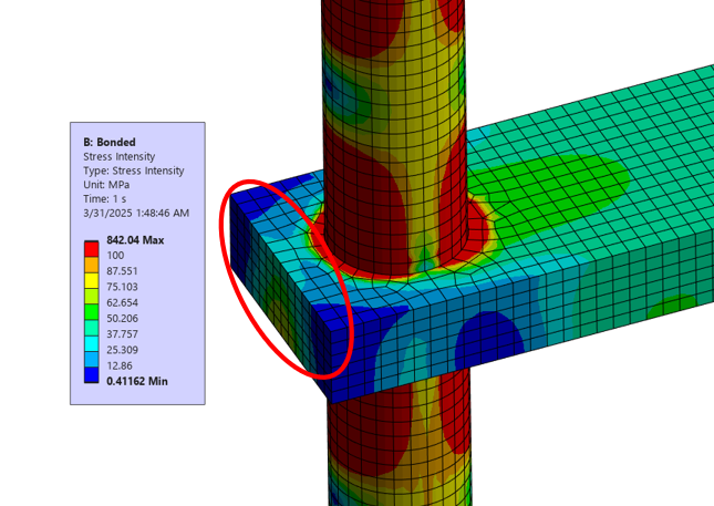
1. Bonded Contact Simulation
When a bonded contact is defined between the pin and the hole, the surfaces move together without relative displacement.
Results:
The stress in the plate behind the pin is well below 100 MPa – The red contours in the stress intensity plot (Fig 2) indicate regions above 100 MPa. The are covered by the red “oval” shows that the bulk stress is well below 100 MPa.
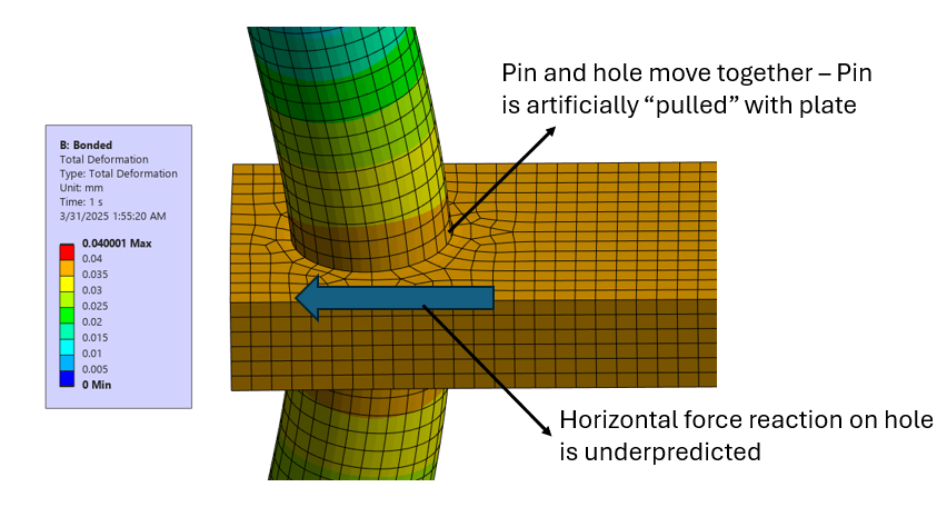
However, this model underpredicts the horizontal force (shear force) reaction on the hole, because it imposes artificial displacement on the pin, as illustrated in Fig 3.
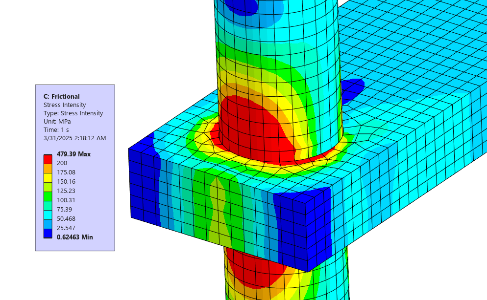
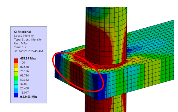
2. Frictional Contact Simulation
Switching to a frictional contact (with a defined coefficient of friction) yields different results.
Results:
- The stress in the plate behind the pin is significantly higher than in the bonded model.
- The plate pushes against the pin on one side while a gap opens on the opposite side, reflecting real-world behavior.
- The Shear force reaction and the shear stress is accurately predicted as acting on approximately one half of the hole.

Conclusion
- Contact selection can drastically affect results. A bonded contact may falsely indicate safety, while a frictional model reveals higher stresses (Though in some cases, incorrect modeling could also lead to underpredicting stresses and hence overdesigned parts).
- FEA is only as good as its inputs. Proper engineering judgment is essential when setting up simulations.
Stay safe, work smart, build well !