Introduction
When analyzing assemblies in Ansys, extracting accurate contact load reactions is essential for evaluating performance, ensuring model realism, and validating engineering decisions — from bolt preload verification to interface force tracking. Ansys Mechanical provides several methods for retrieving contact forces and moments, each with its own advantages and limitations. This article outlines these extraction techniques, compares their use cases, and offers guidance on selecting the most effective method for your simulation goals.
Enabling Contact Load Output in Ansys Mechanical
Before you can extract meaningful contact force or moment data in Ansys Mechanical, you must ensure that certain Output Controls are properly activated. These settings determine which quantities are written to the result file during the solution process — and without them, probes like Contact Tool or Force Reaction may return incomplete or zero values, or may not allow a selection at all.
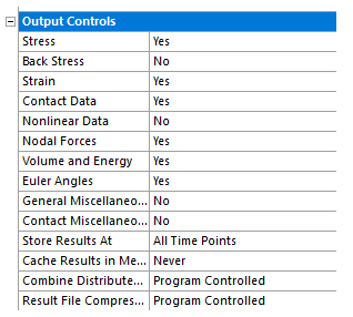
Here are the key Output Controls you should review when contact load reactions are part of your analysis:
Contact Data
- Purpose: Enables writing of contact-specific results (e.g., pressures, penetration, sliding, etc.) to the result file.
- Required For: Using the Contact Tool to evaluate normal and tangential forces across contact regions.
- Location: Under Output Controls > Contact Data → Set to Yes.
Nodal Forces
- Purpose: Stores nodal reaction forces, necessary for accurate evaluation of reaction loads via contact interfaces.
- Required For: Using command snippets like
FSUM, or for extracting reaction forces at supports, remote points, or contact faces. - Location: Output Controls > Nodal Forces → Set to Yes (for all nodes) or Constrained Nodes if only support reactions are needed.
Contact Miscellaneous
- Purpose: Enables contact-based force reaction calculations, especially for target/source-specific force extraction.
- Required For: Evaluating force reactions directly on the contact elements themselves (e.g., normal/tangential forces on bonded or frictional contacts).
- Location: Output Controls > Contact Miscellaneous → Set to Yes.
NOTE: These settings are not step-aware — meaning they apply uniformly across all load steps. They must be set before solving the model to ensure the data is written. Changing them after the solution requires a re-solve.
Activating these controls ensures that contact forces are calculated and stored in the result file, making them available for visualization and post-processing. Failing to turn these on often results in zero-valued probes or missing data — a common issue for those new to contact analysis.
Extracting Contact Forces Using Force Reaction Probes in Ansys
To extract the force or moment transmitted across a contact interface in Ansys Mechanical, you can scope a Force Reaction or Moment Reaction probe directly to a Contact Region. This method sums the nodal forces across the interface, effectively capturing the net load transfer from one part to the other.
Setup Requirements
Before solving, make sure the following Output Controls are set to Yes:
- Contact Data
- Contact Miscellaneous
- Nodal Forces
These ensure the solver writes the necessary element-level data to the result file, enabling accurate post-processing.
Known Limitations
- Rigid bodies in the contact region are not supported; the probe will not solve if the contact involves a rigid surface.
- In Modal and Harmonic Response analyses, this method does not support contact scoping based on element faces or mesh connections.
- Results may be skewed if the scoped contact geometry shares nodes or facets with adjacent bodies; always scope to the contact definition, not general surfaces.
Tips for Clean Results
- Use the Contact Region as the Location Method, not geometry.
- Avoid geometry-based scoping when the interface spans multiple bodies or has complex mesh transitions.
- For section-based extraction, consider using a construction Surface with the appropriate probe settings — but be aware of mesh slicing limitations.
Technical Considerations When Extracting Contact Reactions
When using Force Reaction or Moment Reaction probes to extract loads across contact interfaces, there are several important limitations and configuration nuances that affect accuracy:
Extraction Method Matters
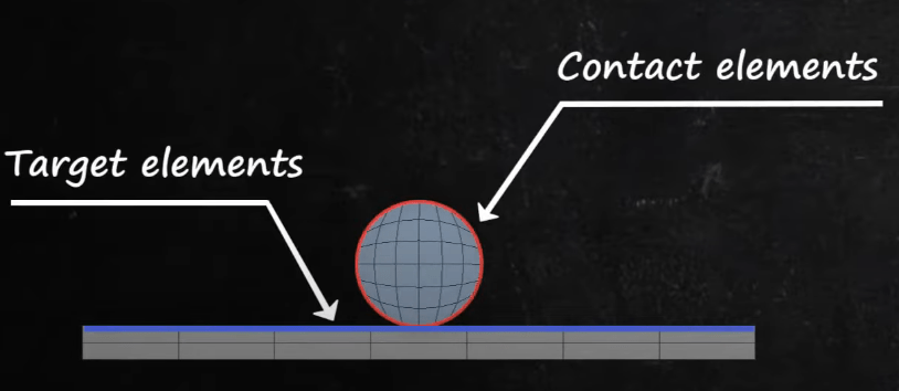
- Set Extraction = Contact (Contact Element) to calculate reactions directly from contact elements. This is the most accurate approach when the contact overlaps with supports or other contact regions.
- Only works with Asymmetric contact (does not work with Symmetric Contact)
- Requires Contact Miscellaneous or General Miscellaneous Output Control set to Yes.
- Not supported for MPC contact or the Target (Underlying Element) side.
- May produce inaccuracies under extreme load magnitudes or large initial interferences.
- Alternatively, Extraction = Contact (Underlying Element) or Target (Underlying Element) will sum internal forces from the elements under the contact region. This is less sensitive to solver artifacts but may include contributions from shared topology or overlapping loads.
Topology & Load Sharing
- Avoid scoping probes to contact regions that share nodes with supports, loads, or other contacts, as these can distort the calculated reaction due to shared internal force paths.
- In transient analyses, inertial and damping forces are included, which may affect interpretation of pure contact transmission.
Moment Calculation Details
- When scoping a Moment Reaction to a contact region, the summation point may default to the centroid and not align precisely with the physical contact face — be aware of this if interpreting rotational effects.
Surface-Based Extraction (Advanced)
- You can use a Surface (cutting plane) as the Location Method to extract contact forces along a section. However:
- Mesh slicing may miss elements or nodes due to tolerance errors or degenerate cuts.
- Do not intersect a boundary condition — this will invalidate reaction data.
- Surface probes do not work with line bodies, joints, springs, or MPC contact.
Other Methods for Contact Load Evaluation
In addition to Force and Moment Reaction probes, Ansys offers two complementary tools for assessing contact behavior and internal load paths:
Contact Tool
The Contact Tool provides a face-by-face breakdown of interface behavior, including:
- Normal and tangential forces
- Penetration and sliding
- Contact status (open, sticking, sliding)
This tool is ideal for diagnosing local effects at the contact interface — such as verifying friction behavior, identifying uneven load distribution, or visually determining joint separation or slippage for a bolted joint — but it does not provide total force or moment values across the interface.
Surface-Based Reaction Probes
When analyzing load transfer through a section (e.g., bolt shafts, beam cross-sections), a Force Reaction probe can be scoped to a construction surface. This technique slices through the mesh and sums reactions from elements on either side.
Limitations:
- Mesh slicing tolerance may cause nodes/elements to be missed, especially with thin or irregular geometries.
- Boundary conditions intersected by the plane invalidate results.
Not supported for line bodies, joints, springs, or MPC contacts.
Conclusion & Practical Takeaways
Extracting meaningful contact load reactions in Ansys Mechanical requires more than just inserting probes — it depends on enabling the right outputs, using the correct extraction methods, and avoiding common pitfalls.
To ensure accurate and reliable results:
- Enable required Output Controls (Contact Data, Contact Miscellaneous, and Nodal Forces) before solving — these settings determine whether the data is even written to the result file.
- Generally avoid scoping probes to geometry (faces, edges, bodies) — this can include unintended nodes or miss internal force paths → Always scope to the actual Contact Region or Boundary Condition for force and moment extraction.
- Use Contact (Contact Element) extraction when other loads/supports overlap the interface — but only with asymmetric contact and proper controls enabled.
- Use the Contact Tool for diagnosing local behavior (sliding, sticking, separation), not for integrated load values.
- Use Surface-based probes for section cuts through bolts or beams, but verify mesh quality and slicing accuracy.
A careful and informed approach to contact load extraction improves not just accuracy — it enhances your understanding of how your model transfers loads, validates your design assumptions, and ultimately results in better engineering decisions.