One of the most common reasons for inaccurate results and convergence issues in contact simulations isn’t a solver setting or material model—it’s bad meshing near contact interfaces. While ANSYS contact algorithms are robust and have significantly improved over the years, they still require proper user input and mesh control to deliver reliable results. Even experienced FEA users overlook this detail, assuming that ANSYS’s contact algorithms will “just figure it out.”
In most cases, they won’t—and assuming they will can lead to inaccurate results. This article explains why mesh matching matters, how it varies by contact type, and what rules of thumb you can apply for robust, accurate simulations.
Why Matching Mesh Across Contacts Matters
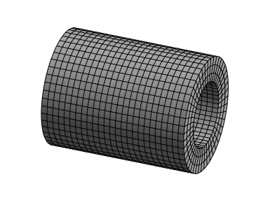
Contact elements in ANSYS are generated between surface facets. If the mesh is coarser on one side and finer on the other, the solver struggles to:
- Correctly compute contact pressure distribution (i.e., the normal stress across the contact interface, which is a component of overall contact stress)
- Predict load transfer direction and magnitude
- Maintain stability and convergence, especially with friction
This becomes more critical in nonlinear contact simulations, such as frictional or transient analyses. Mesh mismatch leads to false gaps, excessive penetration, or solver warnings about unbalanced forces.
Mesh Matching by Contact Type
🔹 Bonded Contacts
- Recommended Ratio: Up to 2:1 element size difference is acceptable (i.e., one surface can have elements twice as large as those on the opposing surface)
- Why: There’s no sliding or separation—the contact behaves like a glued interface. Since the surfaces are locked together, the solver doesn’t need to continuously detect and adjust contact status. This makes the analysis less sensitive to mismatched mesh sizes, as the load is transferred across the interface without requiring precise alignment for friction or sliding behavior.
- Note: Perfect node-to-node alignment is helpful but not required, because when nodes line up exactly across the interface, load transfer becomes more direct and accurate, reducing interpolation errors and improving numerical stability—especially in bonded contacts with high stiffness contrast.
🔹 Frictionless / Rough Contacts
- Recommended Ratio: 1.5:1 or better
- Why: Load is transferred in compression or tangential direction, but without the complexity of sticking or sliding. In frictionless or rough contacts, surfaces may press against each other or slide freely without resisting motion. Since the solver doesn’t have to track and enforce whether the surfaces are “stuck” together (i.e., resisting relative motion), mesh matching is somewhat less critical. However, large mismatches can still lead to uneven pressure distribution or poor load transfer
🔹 Frictional Contacts
- Recommended Ratio: 1:1 element size match
- Why: Frictional behavior depends on accurate tangential stress and sliding detection, which suffers if one side has a much finer mesh.
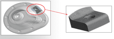
Tip: Even if your CAD surfaces differ in curvature or detail, try to make the mesh resolution at the interface match as closely as possible.
How to Enforce Matching in ANSYS Workbench
Here’s how to ensure mesh compatibility without over-refining your entire model:
✅ 1. Use Named Selections
Scope mesh sizing directly to the contact and target faces using Named Selections. Avoid refining whole bodies unnecessarily. (Also Read: Named Selections in Ansys Workbench)
✅ 2. Use Identical Sizing Controls
Apply the same element size (or mapped face meshing) on both sides of the contact region:
Mesh → Insert → Sizing → Scope to Faces → Set identical Element Size
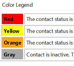
✅ 3. Check Contact Tool for Pressure Quality
After solving, use:
- Contact Tool → Contact Pressure
- Look for smooth, evenly distributed values
- If you see banding, spikes, or checkerboard patterns, mismatched mesh is likely to blame
What Happens If You Don’t Match?
Mismatched contact meshes can lead to:
| Problem | Result | What’s Happening |
|---|---|---|
| Uneven pressure distribution | Spurious stress peaks | Load transfers unevenly due to mismatched surface discretization |
| False contact or separation | Discontinuities in displacement | The solver misinterprets gaps or overlaps between surfaces |
| Solver convergence problems | Increased iterations or divergence | Contact status shifts erratically due to unstable detection |
| Nonphysical sliding behavior | Wrong frictional response | Friction is calculated inconsistently across coarse/fine meshes |
Summary: Practical Rules of Thumb
| Contact Type | Mesh Match Recommendation |
| Bonded | ≤ 2:1 element size ratio |
| Frictionless / Rough | ≤ 1.5:1 preferred |
| Frictional | 1:1 strongly recommended |
✔ Match element sizes where possible
✔ Use local scoping, not global mesh refinement
✔ Verify with the Contact Tool post-solve
Bonus: When to Ignore Matching?
There are cases where close matching isn’t worth the effort. Here are some exmaples:
- Highly stiff parts with negligible relative motion
- Preloaded bolts with bonded interfaces
- Models where contact stress isn’t the primary output