What is a contact in ANSYS?
A contact is a means to define how multiple bodies will interact in ANSYS. It is the only way for ANSYS to know that you are working with an assembly. It is typically defined between two surfaces. You can refer to the contact theory section of this site for more information on contacts.
What happens when a contact is not defined or is not working properly?
If a contact is not defined in an assembly then the components in the assembly will not interact with each other. Bodies can “overlap” or go through each other. This can also happen if a contact is defined but is not working as expected. In the rest of this article we will look at why a contact can misbehave in this manner, and what can be done to remedy this.
I have defined contacts but ANSYS is not seeing them. What now?
The first step is to figure out which contact(s) is under question. In many cases this may be obvious to the user but in some cases it may not be. There are several ways of determining the “health” of contacts within the assembly.
- Use the contact tool: The contact tool is one of the most useful features related to contacts. It is very beneficial, especially for assemblies with multiple contacts. You can right click on connections, hover your mouse pointer on Insert and left click on Contact Tool.
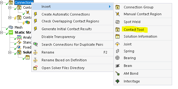
This will insert a contact tool item in the tree. You can now right click on the contact tool and click “Generate initial contact results”. A list of the contacts defined in the model should come up with some information regarding them. One of the most prominent features of the contact tool is the color coding. The explanations for the color codes are listed under the results. The example below shows one such contact. Under status, it says “Far Open” – this gives an indication that there is a large gap between the contacting surfaces and the model will not consider them to be “bonded” as defined.
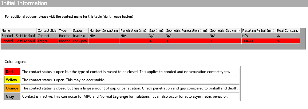
You should definitely look into all “red” contacts. The ones in orange may also be worth looking into. You can select multiple contacts (for example, all the red contacts), right click and select “Go to selected items in tree”. This way you can identify the offending contacts for further study and remediation.
NOTE: If you have defined MPC contacts in the model, they will not appear under the contact tool (more on MPC contacts).
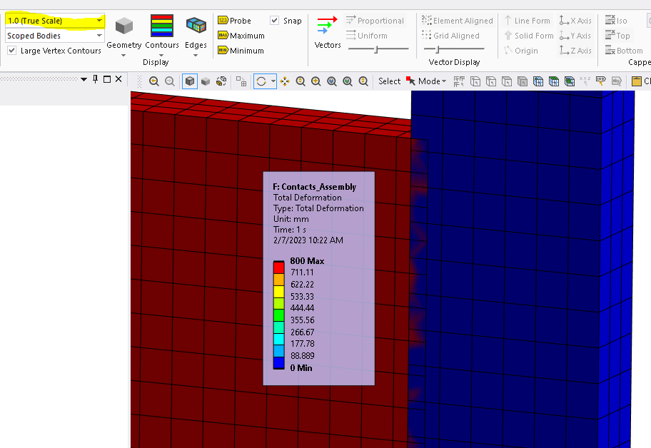
2. Post process results at true scale: This is an obvious thing to do. But sometimes this can be missed. The image below shows clear interference between the components, even though we had a converged solution. In some cases, there would be an unconverged solution, that could give you hints on what components are “flying off” in space.
3. Pay attention to any error / warning messages: If some parts are only meant to be constrained by contacts in a given direction, and the contacts are not being detected then this would usually result in rigid body motion and solver pivot warnings. You may also get an error message such as:
*** ERROR *** CP = 2.016 TIME= 10:26:54
There is at least 1 small equation solver pivot term (e.g., at the UX degree of freedom of node 219). Please check for an insufficiently constrained model.
This message is useful. If you have a large assembly with multiple contacts then you can identify the component / contact with large deformations by the node number. You can do this by creating a named selection with the node number, and then selecting it.
To create a named selection, right click on Model, hover mouse over insert and select Named Selection, as shown below.
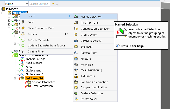
This will create a Named Selection item in the tree. You can then click on “selection”, select “worksheet” as the scoping method. Next, you pick the relevant drop downs from the cells. In our case, we want to create a named selection for node 219. The image below shows the settings for that.

Once you are done with the inputs, click “Generate”. Now, you click on the named selection you just created and ANSYS will highlight it for you, as shown below. You can tell that the grey body is displacing indefinitely.
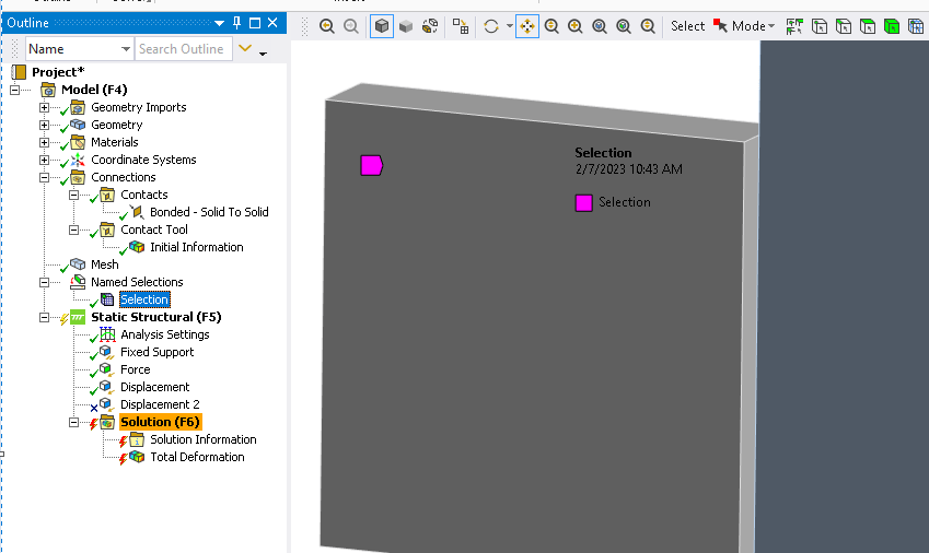
Now that you have identified the offending contact(s) you may take steps to address the issue(s).
Steps to address contact issues
You can take several steps to address the contact issues. Note that one or a combination of these steps may provide you with the desired results.
- Check for gaps in the geometry: You may have unintended at the contact interfaces. This could be addressed by changing the geometry. You may also address geometrical gaps within ANSYS Mechanical using the geometry interface setting (see point 8).
- Check the contact type: Make sure that the contact that you have defined represents what you want. Maybe you wanted a frictional contact (with an initial gap) but defined bonded.
- Check pinball radius: The pinball radius defines the contact search area. An option to define the pinball radius can be found under the advanced contact settings. Here is more information on pinball radius from ANSYS help:
“In the Contact Behavior properties, you can set the Pinball region, which allows you to specify a contact search area commonly referred to as a pinball region. Setting a pinball region can be useful in cases where initially, bodies are far enough away from one another that, by default, the program will not detect that they are in contact. You could then increase the pinball region as needed. Consider an example of a surface body that was generated by offsetting a face of a solid body, possibly leaving a large gap, depending on the thickness. Another example is a large deflection problem where a considerable pinball region is required due to possible large amounts of over penetration. In general though, if you want two regions to be bonded together that may be far apart, you should specify a pinball region that is large enough to ensure that contact indeed occurs.” [1] - Check the mesh: In some cases, poor quality or coarse elements may result in “odd” contact behavior,. Make sure that the mesh is “reasonable”.
- Check the contact detection algorithm: One of the contact settings has to do with selection of the contact detection algorithm. This selection allows the user to select a an algorithm for contact detection to aid in solution convergence. Note that the Nodal-Projected Normal From Contact is the latest and greatest method and is possibly the most robust. It often helps achieve convergence when other methods fail. Selecting this option often ensures the most robust contact behavior and can eliminate oddities.
- Apply the load more “slowly”: Sometimes ANSYS is not able to detect a contact with an initial gap if the load is applied too “quickly”. You can specify sub-steps, to ramp the load slowly. You can also use multiple time steps, and apply a smaller load in the initial time step.
- Apply the load as a displacement instead of force / pressure: A displacement controlled model is typically more robust than a load controller model (More on load vs displacement controlled models).
- Consider “Adjust to Touch” for the interface treatment: For non-linear contacts (frictionless, rough or frictional) you have the option to define the contact interface treatment as part of the Geometry Modification Setting. The following has been taken from ANSYS Help documentation [2]:
- Adjust to Touch: Any initial gaps are closed and any initial penetration is ignored creating an initial stress free state. Contact pairs are “just touching” as illustrated. This setting is useful to make sure initial contact occurs even if any gaps are present (as long as they are within the pinball region). Without using this setting, the bodies may fly apart if any initial gaps exist.
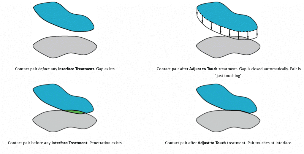
Note:
- The Adjust to Touch option does not lead to uniform contact between concentric cylinders that contain a small initial gap. For this situation, manually specify the gap as an offset in with the Add Offset, No Ramping option.
- Gaps may still be present if the contact pair has regions of differing gaps. When gaps exist, this setting makes sure that initial contact occurs by closing the smallest gap.
References
[1] Advanced Contact Setting – ANSYS Help
[2] Geometric Modifications – ANSYS Help
