Introduction
In a static (steady state) analysis the input loads are not a function of time and inertial effects are not considered. The vice versa is true for dynamic (transient) analysis (Static vs Dynamic Analysis). However, the usage of the word “time” is not limited to transient analyses. We can still have “time steps” in a static analysis. In this article we will briefly discuss the meaning of time as it relates to static analyses.
Time vs Sequence
In a static analysis, time refers to sequence of events. We attribute sequence to time in real life, and thus the same terminology translates to numerical analysis. Imagine a situation in which a flange is installed on a pressure vessel followed by a pressure application. One could set this up as a static structural simulation where:
Time Step 1: Apply Preload (Install Flange)
Time Step 2: Apply Pressure
In this example both time step 1 and time step 2 refer to steady state conditions, but under different loading situations. This is why sometimes the terms time step and load step are used interchangeably.
Another way to think of time in static analysis is how it is used in programming languages. When we define t (time) = 1, it refers to an iteration and not physical time.
Why apply loads in sequence?
One may ask the question why do we need to apply loads in sequence, if they are running a static structural analysis. For example, in the example discussed earlier, why can’t we just have the preload and pressure application happen at the same time? Would it not give the same end result as applying the loads in two separate steps?
The short answer is that superimposing multiple loads in a single step will yield identical results as applying the loads in multiple steps, as long as a single configuration of the geometry is analyzed and the analysis is linear (no sources of non-linearity).
By geometric configurations we imply situations where assembly steps are modeled – For example, the application of preload, introduction of a seal, or removal of weld material.
By linear static analysis we mean that the dependent variable does not impact the independent variables. A structural analysis is linear as long as the stiffness [K] and Force {F} are not functions of the displacements {X}.
The sequence of applied loads can have a significant impact on the response of the system (stresses and strains) if one or both of the above conditions are not met.
What is a Substep in ANSYS?
A sub-step is just as the name suggests a “portion” of the time step. By portion we mean that if at Time Step 1 (T=1s) a force of 1,000 N is applied, it may be applied in increments of loads. For example, there could be 5 sub-steps with 200 N applied in each sub-step. If this is the case, then you would have F=200N at T=0.2s, F=400N at T=0.4s and so on.
Why would you want to have Substeps?
There are two main reasons for this:
- For the ease or necessity of converging to a solution: This is the most common reason for including sub-steps in an analysis. In many cases, the solver would automatically apply the load in increments (sometimes referred to as applying the load “slowly”) because a larger load would not allow for a converged solution. This is almost always the case when running non-linear analyses.
2. To have additional data points: Each substep is associated with a solved results. This means that for a structural analysis you will have explicit stress and strain results at each of the sub steps. Determining how a system responds at intermediate loads is often of interest to the analyst.
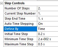
In ANSYS, the “Step Controls” menu provides various options for time step control. By default the Auto Time Stepping is set to “Program Controlled”. This means that the solver will decide if, when and by how much to increment the load. Sometimes though, finer control over the time step settings is desired. This can be done by setting the Auto Time Stepping to “On” and then defining by “Time” or “Substeps”.

