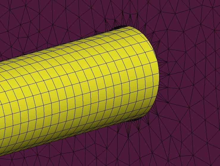
ANSYS Mechanical allows users to generate automatic connections for an assembly upon geometry import. Depending on one’s ability and skill to utilize this feature, this can be a blessing or a curse.
If you are new to ANSYS or just want to explore the automatic connection features more, the following considerations might be of use to you. You can use one or more of these features to make your life easier and make the most of the automatic connection generation feature.
1) Consider the extensive set of options
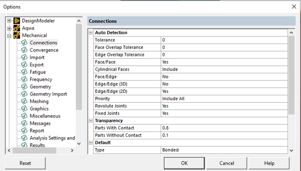
The automatic connections features comes with an extensive set of options. The default settings can almost always be modified to make the generated connections more appropriate and manageable for your model. There are two ways to access these settings. You can go to Mechanical, File, Options, Connections to get this set of options.

The other method of accessing the connection settings is by going to the tree under Mechanical, connections, right click, insert connection group. If you click on the newly created connection group, you will get this under details:

These settings let you control a number of things, some of which can be very useful in preventing un-needed contacts from being generated. The two that I use often are the “tolerance value” (maximum gap between contacting surface) and “search by”. Changing the search by option to parts ensures that contacts are not generated within bodies of multi-body parts.
2) Go to contacts common to multiple bodies
This is a simple but extremely useful feature. You can select multiple bodies in Mechanical, right click and then select “Go to contacts common to selected bodies”. Typically, one would do this for two bodies for which they expect to define contacts. This would highlight all the contacts which the bodies share. At this point you could do what is described below.
3) Create a Group
This is another simple but sometimes underutilized feature. This works for pretty much anything in the Mechanical tree. Once you have identified the contacts common to two bodies of interest, you could right click on the highlighted contacts and click group. This will neatly put the contacts in a folder. You can rename the folder to something appropriate for easy tracking.
4) Rename based on definition
At this point, you might want to also change the contact name to something that is more descriptive, instead of the default “Contact Region”. The name of the contact will now include the name of the two bodies. This is of course only useful if you have already changed the name of the bodies to something descriptive. Note that if you have more than one bodies scoped as contact or target surface then the body names will not appear in the contact definition – Instead it will just say “multiple”.
5) Hide all other bodies
Sometimes, when you are working on a particular contact region, it is desirable (for obvious reasons) to have just the bodies associated with that contact visible and everything else hidden. Well, there is a feature that does just that! Right click on a contact region and select “Hide All Other Bodies”.
6) Use the contact tool
It is a good practice to use the contact tool to view the initial contact statuses before submitting a run. This is even more important when you are using automatically generated contacts. You may be able to identify multiple un-needed contacts in a few minutes and delete or suppress those. Typically, once would start by paying attention to all the contacts that appear as red for the initial status.
If used correctly, these features can make your experience with the automatic connections feature (or ANSYS contacts in general) productive and efficient.
