
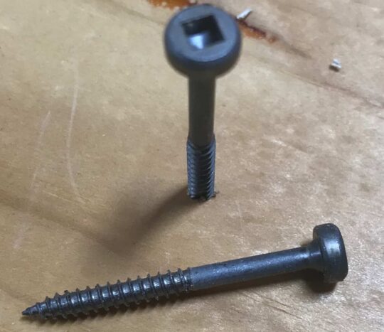

What is Work Hardening ?
Work hardening or strain hardening is a process through which the yield strength and hardness of a metal are increased by plastic deformation. Consider the hypothetical stress strain curve shown below for a metallic specimen:
How to make two cylindrical bodies concentric in Design Modeler
Design Modeler does not have a single command to make two cylindrical bodies concentric (such as the concentric mate command in SolidWorks). However, it is possible to perform this operation in multiple steps. Suppose we have two cylindrical bodies as shown in Figure 1. Step 1: Create planes by centroids Go to create > New…
Read More “How to make two cylindrical bodies concentric in Design Modeler” »
How to make the results legend more readable in ANSYS Workbench
There is a simple, but very useful feature in ANSYS workbench which many users are unaware of. By default, the results legend in ANSYS workbench is fully transparent. This means that if the legend is over a contour, one will not be able to read the legend, as shown in Figure 1. By right clicking…
Read More “How to make the results legend more readable in ANSYS Workbench” »
FEA Theory – Simplified in Seven Points
1) The underlying equation for structural FEA is {F}= [K]*{X} Where {F} is the input load vector and [K] is the global stiffness matrix. {X} is the unknown displacement vector which is solved for at each node in the model. 2) The above gives displacement results only at the nodes. There is no information yet…
Dealing with Convergence Issues – Element Distortion Error
One or more elements have become highly distorted. Excessive distortion of elements is usually a symptom indicating the need for corrective action elsewhere. Try incrementing the load more slowly (increase the number of substeps or decrease the time step size). You may need to improve your mesh to obtain elements with better aspect ratios. Also…
Read More “Dealing with Convergence Issues – Element Distortion Error” »
How to input a stress-strain curve in ANSYS Workbench?
ANSYS and Plastic Strains ANSYS workbench is rather unusual in how it takes inputs for stress-strain curves. Typically, the strain data in stress-strain curves represents total strain. ANSYS workbench requires that the user inputs plastic strain instead of total strain. The total strain must be converted into plastic strain before it can be used with…
Read More “How to input a stress-strain curve in ANSYS Workbench?” »
Converting Total Strain into Elastic and Plastic Components
This spreadsheet lets you convert total strain into its elastic and plastic components. You have to input values for Young’s Modulus, Total Strain and Total Stress – Make sure that the Young’s Modulus and Total Stress have the same units: Strain Converter Stress Total Strain Elastic Strain Plastic Strain 0 0.00000 0.00000 0.00000 10,443 0.00049…
Read More “Converting Total Strain into Elastic and Plastic Components” »
What are integration points in FEA?
An FE solver computes displacement and force results at the element nodes . The shape function is used to interpolate the nodal results onto the interior of the element. Unlike displacements and forces, strains and stresses are not computed at the nodes. They are computed at specific locations called “integration points” within the element. Integration…

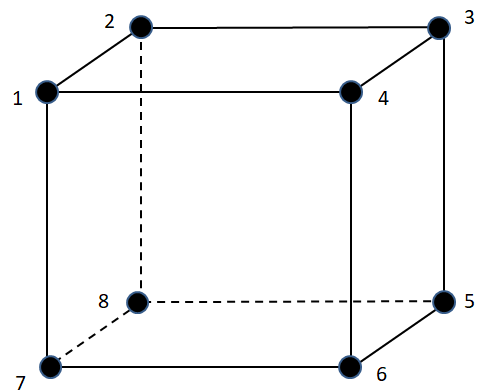
What is a Degree of Freedom?
Degrees of freedom refer to the parameters of a node that may vary independently of each other. In a structural analysis, a node may have up to six degrees of freedom – Three translations and three rotations (one each in X, Y, and Z direction). 3D elements have three DOF – Translations in X, Y,…
Linear vs Quadratic FE Elements
A linear element, or a lower order element is characterized by a linear shape function. The displacements of the mesh region between the nodes vary linearly with the distance between the nodes. Linear elements do not capture bending. A quadratic element, or a higher order element utilizes a non-linear shape function. The displacements between the…
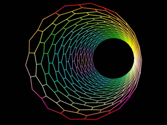
What is a Shape Function?
A Finite Element mesh is the discretization of a continuous geometry into finite parts (elements). An FE solver calculates the displacements at individual nodes of the elements. We are also interested in what happens in the volume (or area for 2-D elements) of the element. But this information is not directly available from the nodal…